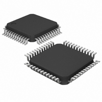
DS1558Y+ Maxim Integrated Products, DS1558Y+ Datasheet

DS1558Y+
Specifications of DS1558Y+
Related parts for DS1558Y+
DS1558Y+ Summary of contents
Page 1
... DS1558Y+ -40°C to +85°C DS1558Y-TRL -40°C to +85°C DS1558Y+TRL -40°C to +85°C + Denotes a lead(Pb)-free/RoHS-compliant device “+” anywhere on the top mark indicates a lead-free device. Note: Some revisions of this device may incorporate deviations from published specifications known as errata. Multiple revisions of any device may be simultaneously available through various sales channels ...
Page 2
PIN DESCRIPTION PIN NAME 1, 13, 39 N.C. No Connection 41 A18 3 A16 4 A14 5 A12 Address Inputs whether or not a RTC ...
Page 3
PIN DES CRIP TION (con PIN NAME Battery BAT1 voltage m ensure ag battery BAT2 “Conditio Active-Low Power-On Reset Output (Open Drain). This pin is an output used to signal that ...
Page 4
IPTI ON The D S1 558 i a full-functio s alarm, watchdog timer, power-on reset, battery monitor, and NV SRAM controller. User access to all registers within the DS1558 is accomplished with a byte-wide interface as shown ...
Page 5
Figure 1. BLOCK DIAGRAM NOTE: ANY U NUSED UPPER ADDRESS PINS MUST BE CONNECTED TO V Table 1. OPERATING MOD > < V ...
Page 6
DATA WRITE MODE The DS1558 is in the write mode whenever referenced to the latter occurring transition of the cycle. and must return inactive for a minimum read or write cycle. Data in must be valid ...
Page 7
CLOCK OPERATIONS Table 2 and the following paragraphs describe the operation of the RTC, alarm, and watchdog functions. Table 2. DS1558 REGISTER MAP ADDR ESS 7FFFF h 10 YEAR 7FFF 7FFFD h X ...
Page 8
READING THE CLOCK When reading the RTC data recomme ed to halt updates to the external set RTC registers. This puts the external registers into a static state, allowing data values changing during the read ...
Page 9
Table 3. ALARM MASK BITS AM4 AM3 AM2 hen regis T ter values m a larm c ond ition ac ...
Page 10
Figure 4. BACKUP MODE ALARM WAVEFORMS USING THE WATCHDOG TIMER The watchdog timer can be used to detect an out-of-control processor. T timer by setting the desired am five watchdog register bits BMB4–BMB0 RB1–RB0 select the resolution, where 00 = ...
Page 11
ABSOLUTE M AXIM Voltage Range on Any Pin Relative to Ground……………………………………………..-0.3V to +6.0V Storage Temperature Range……………………………………………………………….-55C to +125C Soldering T em perature………………………………………….See IPC/JEDEC J-STD-020 Specification This is a stress rating only a nd function sections of this ...
Page 12
DC ELECTRICAL CHARACTERISTICS (V = +3.3V ±10% or +5V ±10 -40°C to +85°C.) CC PARAMETER Active Suppl y Current, +5V Active Suppl y Current, +3.3V TTL Standby, + TTL Standby, +3.3V ( ...
Page 13
READ CYCLE, AC CHARACTERISTICS (V = +3.3V ±10% or +5V ±10 -40°C to +85°C.) (Figure 5) CC PARAMETER Read Cycle Time Address Access Time to DQ Low-Z CE Acce ss Time CE Data Off Time ...
Page 14
WRITE CYCLE, AC CHARACTERISTIC ( 3.3V ±10% or +5V ±10% CC PARAMETER Write Cycle Tim e Address Access Pulse Width WE Pulse Width CE Data Setup Time Data Hold Time Data Hold Time Address Hold ...
Page 15
Figure 6. WRITE CYCLE TIMING, WRITE-ENA Figure 7. WRITE CYCLE TIMING, CHIP-ENABLE CONTROLLED BLE CONTROLLED ...
Page 16
POWER-UP/DOWN CHARACTERISTICS = +5V 10 -40°C o +85°C.) (Figure ARAMETE Before Power-Down V Fall Tim PF(MAX) PF( V ...
Page 17
POWER-UP/DOWN CHARACTERISTICS +3.3V 10 -40°C to +85°C.) (Figure PARAMETER Before Power-Down V Fall Time PF(MAX) PF(MIN) V Rise Time ...
Page 18
... Maxim/Dallas Semiconductor cannot assume responsibility for use of any circuitry other than circuitry entirely embodied in a Maxim/Dallas Semiconductor product. No circuit patent licenses are implied. Maxim/Dallas Semiconductor reserves the right to change the circuitry and specifications without notice at any time The Maxim logo is a registered trademark of Maxim Integrated Products, Inc. The Dallas logo is a registered trademark of Dallas Semiconductor Corporation. vels : es: 5ns at 3 ...


