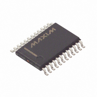
DS1685E-3 Maxim Integrated Products, DS1685E-3 Datasheet - Page 17

DS1685E-3
Manufacturer Part Number
DS1685E-3
Description
IC RTC 3V 64-BIT Y2KC 24-TSSOP
Manufacturer
Maxim Integrated Products
Type
Clock/Calendar/NVSRAM/Y2Kr
Datasheet
1.DS1685S-5.pdf
(34 pages)
Specifications of DS1685E-3
Memory Size
242B
Time Format
HH:MM:SS (12/24 hr)
Date Format
YY-MM-DD-dd
Interface
Parallel
Voltage - Supply
2.7 V ~ 3.7 V
Operating Temperature
0°C ~ 70°C
Mounting Type
Surface Mount
Package / Case
24-TSSOP
Lead Free Status / RoHS Status
Contains lead / RoHS non-compliant
Other names
DS1685E3
Available stocks
Company
Part Number
Manufacturer
Quantity
Price
Company:
Part Number:
DS1685E-3
Manufacturer:
DALLAS
Quantity:
51
Part Number:
DS1685E-3
Manufacturer:
DALLAS
Quantity:
20 000
Company:
Part Number:
DS1685E-3+
Manufacturer:
Maxim
Quantity:
400
Company:
Part Number:
DS1685E-3+
Manufacturer:
Maxim
Quantity:
206
Company:
Part Number:
DS1685E-3+T&R
Manufacturer:
MAXIM
Quantity:
11
Figure 4. Update-Ended And Periodic-Interrupt Relationship
EXTENDED FUNCTIONS
The extended functions provided by the DS1685/DS1687 that are new to the RAMified RTC family are accessed by
a software-controlled bank-switching scheme, as illustrated in Figure 5. In bank 0, the clock/calendar registers and
50 bytes of user RAM are in the same locations as for the DS1287. As a result, existing routines implemented
within BIOS, DOS, or application software packages can gain access to the DS1685/DS1687 clock registers with
no changes. Also in bank 0, an extra 64 bytes of RAM are provided at addresses just above the original locations
for a total of 114 directly addressable bytes of user RAM.
UIP
PF
UF
t
t
PI
BUC
= PERIODIC INTERRUPT TIME INTERNAL PER TABLE 3.
= DELAY BEFORE UPDATE CYCLE = 244s.
t
BUC
17 of 34
1 second
t
PI
t
PI/2
DS1685/DS1687 3V/5V Real-Time Clocks
t
PI/2


