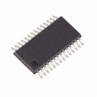
MAXQ3181-RAN+ Maxim Integrated Products, MAXQ3181-RAN+ Datasheet - Page 74

MAXQ3181-RAN+
Manufacturer Part Number
MAXQ3181-RAN+
Description
IC AFE POLYPHASE LO-PWR 28-TSSOP
Manufacturer
Maxim Integrated Products
Datasheet
1.MAXQ3181-RAN.pdf
(84 pages)
Specifications of MAXQ3181-RAN+
Number Of Channels
8
Power (watts)
35mW
Voltage - Supply, Analog
3.3V
Voltage - Supply, Digital
3.3V
Package / Case
28-TSSOP
Lead Free Status / RoHS Status
Lead free / RoHS Compliant
Number Of Bits
-
Low-Power, Active Energy, Polyphase AFE
This register is a mirror of a CPU register in the MAXQ3181. This register should not be modified by supervisory
code. This register specifies the time, in CPU clocks, that the ADC must wait after switching analog mux inputs
before beginning its conversion. This register defaults to 0x2F (47 decimal), which specifies a 48 CPU clock-cycle
delay from analog mux switching to the start of conversion.
This register is a mirror of a CPU register in the MAXQ3181. This register configures the SPI port of the MAXQ3181.
74
Bit:
Name:
Reset:
Bit:
Name:
Reset:
Bit:
Name:
Reset:
BIT
5:3
______________________________________________________________________________________
7
6
2
1
0
CKPHA
CKPOL
NAME
ESPII
CHR
SAS
—
ESPII
15
—
—
7
1
7
Enable SPI Interrupt. If set, arrival of a character on the SPI bus causes a CPU interrupt.
SPI Slave Select Polarity. If clear, SSEL is assumed to be active low; if set, SSEL is assumed to be
active high.
Reserved.
SPI Character Length. If clear, characters on the SPI bus are assumed to be 8 bits; if set, characters on
the SPI bus are assumed to be 16 bits.
SPI Clock Phase. If clear, data is sampled on the leading edge of the clock (low-to-high if the clock is
active high, and high-to-low if the clock is active low). If set, data is sampled on the trailing edge of the
clock (high-to-low if the clock is active high, and low-to-high if the clock is active low).
SPI Clock Polarity. If clear, the clock is assumed to be active high; if set, the clock is assumed to be
active low.
SAS
14
—
6
6
0
13
—
—
5
5
0
ADC Settling Time High Byte
ADC Settling Time Low Byte
12
—
—
4
4
0
FUNCTION
ADC Settling Time (R_ADCACQ) (0x050)
0x2F
SPI Configuration (R_SPICF) (0x052)
11
—
—
3
3
0
CHR
10
—
2
2
0
CKPHA
—
9
1
1
0
CKPOL
—
8
0
0
0


