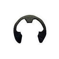
21045-3 TE Connectivity, 21045-3 Datasheet - Page 3

21045-3
Manufacturer Part Number
21045-3
Description
Retaining Ring
Manufacturer
TE Connectivity
Specifications of 21045-3
Rohs Compliant
Yes
For Use With
Tyco Crimp Tools
Lead Free Status / Rohs Status
Compliant
Rev H
Step 1
Step 2
Step 3
Step 4
Note: Not to Scale
Handles Closed
STRIP Slot
Cutting and Stripping Unshielded Flat Oval Cable
Unshielded
Flat Oval
Cable
CUT Slot
Die Cable
Stop
Figure 4
Cable Strip Length
12.7–14.3 [.50–.56] (Ref)
Modular Plug Hand Tool (Premium Grade) 231652–[ ]
4. TERMINATION PROCEDURE
Before proceeding with the termination procedure,
check to make sure that the cable and modular plug
are compatible, and that cable polarity is correctly
maintained for the specific application.
Before proceeding with the termination procedure for
high performance modular plugs, refer to 114–6053
for preparation techniques to ensure high
performance levels.
Refer to Figure 5, and proceed as follows:
CAUTION
1. Hold modular plug as shown (locking latch
facing UP). Insert cable into modular plug until fully
bottomed.
2. Open tool handles. Insert modular plug
assembly fully into die cavity. When using a die set
color coded with green, orange, or blue, make sure
that the modular plug locking latch snaps into
position. When using a die set color coded with
black, violet, or white, make sure that the modular
plug bottoms in the die cavity but the locking latch
does not snap into position.
3. Hold the modular plug in the fully seated
position, and squeeze tool handles until ratchet
releases.
NOTE
4. Depress the modular plug locking latch (if
applicable), and remove terminated modular plug
assembly from the tool.
5. Inspect the modular plug assembly for proper
crimp height using a dial indicator or digital
indicator with needle–point probes, or a Crimp
Height Gage 904170–1 according to 408–4389.
Figure 6 shows a cross–section of a typical
terminated modular plug, proper crimp height
dimension, and required location of the conductors.
A visual inspection through the plastic housing of
the modular plug should reveal whether the
conductors are within acceptable range.
NOTE
NOTE
Failure to fully seat the modular plug assembly in
the die cavity will cause the indenter to mis–align
with the internal strain reliefs of the modular plug,
which may result in damage to the die set.
When crimping, make sure to hold the modular
plug in the fully seated position to prevent the
modular plug from pushing out during the
termination procedure.
For specific information concerning inspection
requirements, refer to 114–6016 for standard and
blue (small conductor) modular plugs and
114–6053 for high performance modular plugs.
Once a termination has been made, DO NOT
re–terminate the modular plug. Replace damaged
modular plugs with new ones.
408–9767
3 of 7


