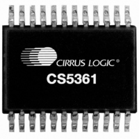
CS5361-KZZ Cirrus Logic Inc, CS5361-KZZ Datasheet - Page 16

CS5361-KZZ
Manufacturer Part Number
CS5361-KZZ
Description
IC ADC AUD 114DB 204KHZ 24-TSSOP
Manufacturer
Cirrus Logic Inc
Datasheet
1.CS5361-KZZ.pdf
(23 pages)
Specifications of CS5361-KZZ
Package / Case
24-TSSOP
Number Of Converters
2
Number Of Bits
24
Sampling Rate (per Second)
204k
Data Interface
Serial
Power Dissipation (max)
235mW
Voltage Supply Source
Analog and Digital
Operating Temperature
-10°C ~ 70°C
Mounting Type
Surface Mount
Conversion Rate
192 KSPS
Resolution
24 bit
Number Of Adc Inputs
2
Operating Supply Voltage
5 V
Maximum Operating Temperature
+ 70 C
Minimum Operating Temperature
- 10 C
Mounting Style
SMD/SMT
Power Consumption
135 mW
Supply Voltage (max)
5.25 V
Supply Voltage (min)
4.75 V
Lead Free Status / RoHS Status
Lead free / RoHS Compliant
For Use With
598-1547 - BOARD EVAL FOR CS5361 STEREO ADC
Lead Free Status / Rohs Status
Lead free / RoHS Compliant
Other names
598-1087-5
Available stocks
Company
Part Number
Manufacturer
Quantity
Price
Company:
Part Number:
CS5361-KZZ
Manufacturer:
CRYSTAL/38
Quantity:
390
Part Number:
CS5361-KZZ
Manufacturer:
CIRRUS
Quantity:
20 000
Company:
Part Number:
CS5361-KZZR
Manufacturer:
NI
Quantity:
101
4.0 APPLICATIONS
4.1
The output sample rate, Fs, can be adjusted from 2 kHz to 204 kHz. The CS5361 must be set to the proper speed
mode via the mode pins, M1 and M0. Refer to Table 1.
4.2
The device supports operation in either Master Mode, where the left/right and serial clocks are synchronously gen-
erated on-chip, or Slave Mode, which requires external generation of the left/right and serial clocks. The device also
includes a master clock divider in Master Mode where the master clock will be internally divided prior to any other
internal circuitry when MDIV is enabled, set to logic 1. In Slave Mode, the MDIV pin needs to be disabled, set to logic
0.
4.2.1
LRCK and SCLK operate as inputs in Slave mode. The left/right clock must be synchronously derived from the mas-
ter clock and be equal to Fs. It is also recommended that the serial clock be synchronously derived from the master
clock and be equal to 64x Fs to maximize system performance. Refer to Table 2 for required clock ratios.
16
MCLK/LRCK Ratio
SCLK/LRCK Ratio
M1 (Pin 14)
Operational Mode/Sample Rate Range Select
System Clocking
0
0
1
1
Slave Mode
M0 (Pin 13)
0
1
0
1
Fs = 2 kHz to 51 kHz
Single Speed Mode
32x, 64x, 128x
Table 2. CS5361 Slave Mode Clock Ratios
256x, 512x
Table 1. CS5361 Mode Control
Double Speed Mode
Single Speed Mode
Quad Speed Mode
Reserved
MODE
Fs = 50 kHz to 102 kHz
Double Speed Mode
128x, 256x
32x, 64x
Output Sample Rate (Fs)
100 kHz - 204 kHz
50 kHz - 102 kHz
2 kHz - 51 kHz
Fs = 100 kHz to 204 kHz
Quad Speed Mode
32x, 64x
128x
CS5361
DS467F2


