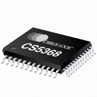
CS5368-CQZ Cirrus Logic Inc, CS5368-CQZ Datasheet - Page 7

CS5368-CQZ
Manufacturer Part Number
CS5368-CQZ
Description
IC ADC 8CH 114DB 216KHZ 48-LQFP
Manufacturer
Cirrus Logic Inc
Datasheet
1.CS5368-CQZ.pdf
(42 pages)
Specifications of CS5368-CQZ
Package / Case
48-LQFP
Number Of Converters
1
Number Of Bits
24
Sampling Rate (per Second)
216k
Data Interface
Serial
Power Dissipation (max)
1.12W
Voltage Supply Source
Analog and Digital
Operating Temperature
-40°C ~ 85°C
Mounting Type
Surface Mount
Conversion Rate
192 KSPS
Resolution
24 bit
Number Of Adc Inputs
8
Operating Supply Voltage
5 V
Maximum Operating Temperature
+ 85 C
Minimum Operating Temperature
- 10 C
Mounting Style
SMD/SMT
Power Consumption
680 mW
Supply Voltage (max)
5.25 V
Supply Voltage (min)
4.75 V
Lead Free Status / RoHS Status
Lead free / RoHS Compliant
For Use With
598-1157 - BOARD EVAL FOR CS5368 192KHZ ADC
Lead Free Status / Rohs Status
Lead free / RoHS Compliant
Other names
598-1090
Available stocks
Company
Part Number
Manufacturer
Quantity
Price
Company:
Part Number:
CS5368-CQZ
Manufacturer:
CIRRUS
Quantity:
30
Part Number:
CS5368-CQZ
Manufacturer:
CIRRUS
Quantity:
20 000
Company:
Part Number:
CS5368-CQZR
Manufacturer:
Cirrus Logic Inc
Quantity:
10 000
DS624F4
Stand-Alone Mode
SDOUT1/TDM
SDOUT3/TDM
AIN2+, AIN2-
AIN4+, AIN4-
AIN3+, AIN3-
AIN7+, AIN7-
AIN8+, AIN8-
AIN6+, AIN6-
AIN5+, AIN5-
AIN1+, AIN1-
Pin Name
CLKMODE
REF_GND
LRCK/FS
SDOUT4
SDOUT2
MCLK
SCLK
OVFL
FILT+
MDIV
GND
DIF1
DIF0
XTO
VLC
RST
VLS
XTI
VQ
VD
M1
M0
VA
VX
Pin #
11,12
13,14
15,16
17,18
43,44
45,46
47,48
10,19
29,32
1,2
3,8
4,9
20
21
22
23
24
25
26
27
28
30
31
33
35
36
41
34
37
38
39
40
42
5
6
7
Differential Analog (Inputs) - Audio signals are presented differently to the delta sigma modula-
tors via the AIN+/- pins.
Ground (Input) - Ground reference. Must be connected to analog ground.
Analog Power (Input) - Positive power supply for the analog section
Reference Ground (Input) - For the internal sampling circuits. Must be connected to analog
ground.
Positive Voltage Reference (Output) - Reference voltage for internal sampling circuits.
Quiescent Voltage (Output) - Filter connection for the internal quiescent reference voltage.
Crystal Oscillator Power (Input) - Also powers control logic to enable or disable oscillator cir-
cuits.
Crystal Oscillator Connections (Input/Output) - I/O pins for an external crystal which may be
used to generate MCLK.
System Master Clock (Input/Output) - When a crystal is used, this pin acts as a buffered MCLK
Source (Output). When the oscillator function is not used, this pin acts as an input for the system
master clock. In this case, the XTI and XTO pins must be tied low.
Serial Audio Channel Clock (Input/Output)
In I²S Mode, Serial Audio Channel Select. When low, the odd channels are selected.
In LJ Mode, Serial Audio Channel Select. When high, the odd channels are selected.
In TDM Mode, a frame sync signal. When high, it marks the beginning of a new frame of serial
audio samples. In Slave Mode, this pin acts as an input pin.
Main timing clock for the Serial Audio Interface (Input/Output) - During Master Mode, this pin
acts as an output, and during Slave Mode it acts as an input pin.
Serial Audio Data (Output) - Channels 7,8.
Serial Audio Data (Output) - Channels 3,4.
Serial Audio Interface Power (Input) - Positive power for the serial audio interface.
Serial Audio Data (Output) - Channels 1,2.
Serial Audio Data (Output) - Channels 5,6. TDM is complementary TDM data.
Digital Power (Input) - Positive power supply for the digital section.
Control Port Interface Power(Input) - Positive power for the control port interface.
Overflow (Output, open drain) - Detects an overflow condition on both left and right channels.
Reset (Input) - The device enters a low power mode when low.
CLKMODE (Input) - Setting this pin HIGH places a divide-by-1.5 circuit in the MCLK path to the
core device circuitry.
DIF1, DIF0 (Input) - Inputs of the audio interface format.
Mode Selection (Input) - Determines the operational mode of the device.
MCLK Divider (Input) - Setting this pin HIGH places a divide-by-2 circuit in the MCLK path to the
core device circuitry.
Pin Description
CS5368
7


