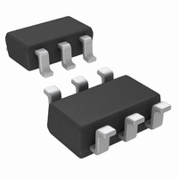
ADCS7477AIMF/NOPB National Semiconductor, ADCS7477AIMF/NOPB Datasheet - Page 20

ADCS7477AIMF/NOPB
Manufacturer Part Number
ADCS7477AIMF/NOPB
Description
IC ADC 10BIT 1MSPS SOT-23-6
Manufacturer
National Semiconductor
Series
PowerWise®r
Datasheet
1.ADCS7478AIMFNOPB.pdf
(24 pages)
Specifications of ADCS7477AIMF/NOPB
Number Of Bits
10
Sampling Rate (per Second)
1M
Data Interface
MICROWIRE™, QSPI™, Serial, SPI™
Number Of Converters
1
Power Dissipation (max)
17.5mW
Voltage Supply Source
Single Supply
Operating Temperature
-40°C ~ 85°C
Mounting Type
Surface Mount
Package / Case
SOT-23-6
Lead Free Status / RoHS Status
Lead free / RoHS Compliant
Other names
ADCS7477AIMF
ADCS7477AIMFTR
ADCS7477AIMFTR
Available stocks
Company
Part Number
Manufacturer
Quantity
Price
Part Number:
ADCS7477AIMF/NOPB
Manufacturer:
TI/德州仪器
Quantity:
20 000
www.national.com
10.0 EXITING SHUTDOWN MODE
To exit shutdown mode, bring CS back low. Upon bringing
CS low, the ADCS7476/77/78 will begin powering up. Power
up typically takes 1 µs. This microsecond of power-up delay
results in the first conversion result being unusable. The sec-
ond conversion performed after power-up, however, is valid,
as shown in
If CS is brought back high before the 10th falling edge of
SCLK, the device will return to shutdown mode. This is done
to avoid accidentally entering normal mode as a result of
noise on the CS line. To exit shutdown mode and remain in
normal mode, CS must be kept low until after the 10th falling
edge of SCLK. The ADCS7476/77/78 will be fully powered-
up after 16 SCLK cycles.
11.0 POWER-UP TIMING
The ADCS7476/77/78 typically requires 1 µs to power up, ei-
ther after first applying V
from shutdown mode. This corresponds to one "dummy" con-
version for any SCLK frequency within the specifications in
this document. After this first dummy conversion, the AD-
CS7476/77/78 will perform conversions properly. Note that
the t
conversion and the second valid conversion.
12.0 STARTUP MODE
When the V
may power up in either of the two modes: normal or shutdown.
As such, one dummy conversion should be performed after
start-up, exactly as described in Section
TIMING. The part may then be placed into either normal mode
or the shutdown mode, as described in Section
MODE
13.0 POWER CONSIDERATIONS
There are three concerns relating to the power supply of these
products: the effects of power supply noise upon the conver-
sion process, the digital output loading effects upon the con-
QUIET
and Section
time must still be included between the first dummy
DD
Figure
supply is first applied, the ADCS7476/77/78
11.
9.0 SHUTDOWN
DD
, or after returning to normal mode
MODE.
11.0 POWER-UP
FIGURE 10. Entering Shutdown Mode
FIGURE 11. Entering Normal Mode
8.0 NORMAL
20
version process and managing total power consumption of
the product.
13.1 Power Supply Noise
Since the reference voltage of the ADCS7476/77/78 is the
reference voltage, any noise greater than 1/2 LSB in ampli-
tude will have some effect upon the converter noise perfor-
mance. This effect is proportional to the input voltage level.
The power supply should receive all the considerations of a
reference voltage as far as stability and noise is concerned.
Using the same supply voltage for these devices as is used
for digital components will lead to degraded noise perfor-
mance.
13.2 Digital Output Effect Upon Noise
The charging of any output load capacitance requires current
from the digital supply, V
the supply to charge the output capacitance will cause voltage
variations at the ADC supply line. If these variations are large
enough, they could degrade SNR and SINAD performance of
the ADC. Similarly, discharging the output capacitance when
the digital output goes from a logic high to a logic low will dump
current into the die substrate, causing "ground bounce" noise
in the substrate that will degrade noise performance if that
current is large enough. The larger the output capacitance,
the more current flows through the device power supply line
and die substrate and the greater is the noise coupled into the
analog path.
The first solution to keeping digital noise out of the power
supply is to decouple the supply from any other components
or use a separate supply for the ADC. To keep noise out of
the supply, keep the output load capacitance as small as
practical. If the load capacitance is greater than 50 pF, use a
100 Ω series resistor at the ADC output, located as close to
the ADC output pin as practical. This will limit the charge and
discharge current of the output capacitance and improve
noise performance. Since the series resistor and the load ca-
DD
. The current pulses required from
20057716
20057717


