LTC2170IUKG-14#PBF Linear Technology, LTC2170IUKG-14#PBF Datasheet - Page 3
LTC2170IUKG-14#PBF
Manufacturer Part Number
LTC2170IUKG-14#PBF
Description
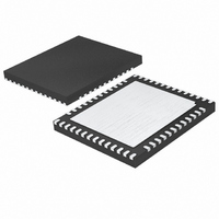
IC ADC 14BIT SER/PAR 25M 52-QFN
Manufacturer
Linear Technology
Datasheet
1.LTC2172IUKG-14PBF.pdf
(34 pages)
Specifications of LTC2170IUKG-14#PBF
Number Of Bits
14
Sampling Rate (per Second)
25M
Data Interface
Serial, Parallel
Number Of Converters
4
Power Dissipation (max)
243mW
Voltage Supply Source
Analog and Digital
Operating Temperature
-40°C ~ 85°C
Mounting Type
Surface Mount
Package / Case
52-WFQFN Exposed Pad
Number Of Elements
4
Resolution
14Bit
Sample Rate
25MSPS
Input Polarity
Bipolar
Input Type
Voltage
Rated Input Volt
±0.5/±1V
Differential Input
Yes
Power Supply Requirement
Single
Single Supply Voltage (typ)
1.8V
Single Supply Voltage (min)
1.7V
Single Supply Voltage (max)
1.9V
Dual Supply Voltage (typ)
Not RequiredV
Dual Supply Voltage (min)
Not RequiredV
Dual Supply Voltage (max)
Not RequiredV
Power Dissipation
243mW
Differential Linearity Error
±0.8LSB
Integral Nonlinearity Error
±2.75LSB
Operating Temp Range
-40C to 85C
Operating Temperature Classification
Industrial
Mounting
Surface Mount
Pin Count
52
Package Type
QFN EP
Input Signal Type
Differential
Lead Free Status / RoHS Status
Lead free / RoHS Compliant
Available stocks
Company
Part Number
Manufacturer
Quantity
Price


CONVERTER CHARACTERISTICS
PARAMETER
Resolution (No Missing Codes)
Integral Linearity Error
Differential Linearity Error
Offset Error
Gain Error
Offset Drift
Full-Scale Drift
Gain Matching
Offset Matching
Transition Noise
temperature range, otherwise specifi cations are at T
ANALOG INPUT
SYMBOL PARAMETER
V
V
V
I
I
I
I
t
t
CMRR
BW-3B
specifi cations are at T
IN(CM)
IN1
IN2
IN3
AP
JITTER
IN
IN(CM)
SENSE
Analog Input Range (A
Analog Input Common Mode (A
External Voltage Reference Applied to SENSE
Analog Input Common Mode Current
Analog Input Leakage Current (No Encode)
PAR/SER Input Leakage Current
SENSE Input Leakage Current
Sample-and-Hold Acquisition Delay Time
Sample-and-Hold Acquisition Delay Jitter
Analog Input Common Mode Rejection Ratio
Full-Power Bandwidth
A
= 25°C. (Note 5)
CONDITIONS
Differential Analog Input (Note 6)
Differential Analog Input
(Note 7)
Internal Reference
External Reference
Internal Reference
External Reference
External Reference
External Reference
IN
+
– A
The
IN
–
IN
l
)
+
denotes the specifi cations which apply over the full operating temperature range, otherwise
+ A
IN
–
)/2
A
CONDITIONS
1.7V < V
Differential Analog Input (Note 8)
External Reference Mode
Per Pin, 65Msps
Per Pin, 40Msps
Per Pin, 25Msps
0 < A
0 < PAR/SER < V
0.625 < SENSE < 1.3V
Figure 6 Test Circuit
= 25°C. (Note 5)
IN
The
l
l
l
l
l
+
, A
DD
–3.25
IN
l
MIN
–0.8
–2.5
–12
< 1.9V
14
–
denotes the specifi cations which apply over the full operating
< V
LTC2172-14
DD
DD
±0.3
±0.2
TYP
±20
±35
±25
1.2
±1
±3
–1
–1
±3
MAX
3.25
LTC2171-14/LTC2170-14
0.8
0.5
12
–2.75
MIN
–0.8
–2.5
–12
14
l
l
l
l
l
l
LTC2171-14
V
CM
±0.3
±0.2
TYP
±20
±35
±25
1.2
±1
±3
–1
–1
±3
0.625
MIN
– 100mV
–1
–3
–6
MAX
2.75
0.8
0.5
12
LTC2172-14/
1 to 2
1.250
0.15
TYP
V
–2.75
800
–0.8
–2.5
81
50
31
80
MIN
–12
CM
0
14
LTC2170-14
±0.3
±0.2
TYP
±20
±35
±25
1.2
±1
±3
–1
–1
±3
V
CM
1.300
MAX
+ 100mV
1
3
6
MAX
2.75
0.8
0.5
12
21721014fa
LSB
ppm/°C
ppm/°C
UNITS
UNITS
ps
μV/°C
3
%FS
%FS
%FS
LSB
LSB
V
MHz
Bits
RMS
RMS
mV
mV
P-P
μA
μA
μA
μA
μA
μA
dB
ns
V
V
Related parts for LTC2170IUKG-14#PBF
Image
Part Number
Description
Manufacturer
Datasheet
Request
R

Part Number:
Description:
IC ADC 12BIT SER/PAR 25M 52-QFN
Manufacturer:
Linear Technology
Datasheet:
Part Number:
Description:
IC ADC 12BIT SER/PAR 25M 52-QFN
Manufacturer:
Linear Technology
Datasheet:
Part Number:
Description:
IC ADC 14BIT SER/PAR 25M 52-QFN
Manufacturer:
Linear Technology
Datasheet:

Part Number:
Description:
CD ROM LINEARVIEW DATASHEETS
Manufacturer:
Linear Technology

Part Number:
Description:
Standalone Linear Li-Ion Battery Charger with Thermal Regulation in ThinSOT
Manufacturer:
Linear Technology Corporation
Datasheet:
Part Number:
Description:
Low noise, high frequency, 8th order linear phase lowpass filter
Manufacturer:
Linear Technology Corporation
Datasheet:
Part Number:
Description:
Manufacturer:
Linear Technology Corporation
Datasheet:
Part Number:
Description:
Manufacturer:
Linear Technology Corporation
Datasheet:
Part Number:
Description:
Manufacturer:
Linear Technology Corporation
Datasheet:
Part Number:
Description:
Manufacturer:
Linear Technology Corporation
Datasheet:
Part Number:
Description:
Manufacturer:
Linear Technology Corporation
Datasheet:
Part Number:
Description:
Manufacturer:
Linear Technology Corporation
Datasheet:
Part Number:
Description:
Manufacturer:
Linear Technology Corporation
Datasheet:
Part Number:
Description:
Dual and Quad, JFET Input Precision High Speed Op Amps
Manufacturer:
Linear Technology Corporation
Datasheet:
Part Number:
Description:
Manufacturer:
Linear Technology Corporation
Datasheet: