532808-1 TE Connectivity, 532808-1 Datasheet - Page 3
532808-1
Manufacturer Part Number
532808-1
Description
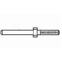
HDI GUIDE PIN KIT
Manufacturer
TE Connectivity
Series
AMP-HDI Seriesr
Datasheet
1.1-532428-1.pdf
(6 pages)
Specifications of 532808-1
Rohs Compliant
YES
Product Type
Guide Pins
Number Of Positions / Contacts
4
Pitch
2.54 mm
Mounting Style
Through Hole
Accessory Type
Guide Pin Kit
Body Material
Stainless Steel
Body Finish
Passivated
Product Line
AMP-HDI, TBC
Guide Pin Type
Standard
For Use In
Center Guide Holes
Thread Length (mm [in])
10.79 [0.425]
Government/industry Qualification
No
Rohs/elv Compliance
RoHS compliant, ELV compliant
Lead Free Solder Processes
Not relevant for lead free process
Rohs/elv Compliance History
Always was RoHS compliant
Lead Free Status / Rohs Status
Details


Unm ating force.
Contact retention.
Contact engaging force.
Contact separating force.
Durability.
Resistance to soldering heat.
Insertion force, ACTION PIN.
Retention force, ACTION PIN.
Torque, ACTION PIN.
Therm al shock.
Hum idity-tem perature cycling.
Rev C
Test Description
No physical dam age.
40 pounds m axim um per pin.
Pin shall not dislodge from printed
.4 ounces m inim um average per
contact.
Contacts shall not dislodge from its
norm al locking position.
4 ounces m axim um per contact.
.1 ounce m inim um .
No physical dam age.
.020 ohm s m axim um term ination
resistance, low level.
Contact separation force.
wiring board.
Pin shall not m ove or dislodge from
printed wiring board.
.020 ohm s m axim um term ination
resistance, low level.
1000 m egohm s final insulation
resistance.
ENVIRONMENTAL
Figure 1 (end)
Requirem ent
Measure force to engage using
Size 3 tim es using gage 2, insert
Subject term inal posts m ounted on
Fully insert pin into printed wiring
Measure force necessary to unm ate
connector assem bly.
Calculate force per contact.
TE Spec 109-42, Condition A.
Apply axial load of 3 pounds to
individual contacts.
TE Spec 109-30.
gage 2.
See Figure 4.
TE Spec 109-35.
gage 1 and m easure force to
separate.
See Figure 4.
TE Spec 109-35.
Mate and unm ate pin and
receptacle connectors for 250
cycles.
TE Spec 109-27.
printed circuit boards to solder bath
at 260 ±5 C for 10 ±2 seconds.
Spec 109-63-3.
board hole.
Apply an axial load of 10 pounds for
10 seconds.
Apply 2 inch ounces for 10 seconds
in both directions.
Subject m ated connectors to 5
cycles between -65 and 125°C.
TE Spec 109-22.
Subject m ated connectors to 10
hum idity-tem perature cycles
between 25 and 65°C at 95% RH.
TE Spec 109-23, Method III,
Condition B, less steps 7 a and 7b.
Procedure
108-9063
3 of 6
Related parts for 532808-1
Image
Part Number
Description
Manufacturer
Datasheet
Request
R

Part Number:
Description:
532-AG10D-ES=SOCKET ASSY.
Manufacturer:
TE Connectivity
Datasheet:
Part Number:
Description:
532-AG11D-ES=SOCKET ASSEMBLY
Manufacturer:
TE Connectivity
Datasheet:


Part Number:
Description:
DIP SOCKET, 32POS, THROUGH HOLE
Manufacturer:
TE Connectivity
Datasheet:
Part Number:
Description:
DIP Socket
Manufacturer:
TE Connectivity
Datasheet:


Part Number:
Description:
Manufacturer:
TE Connectivity
Datasheet:


Part Number:
Description:
Manufacturer:
TE Connectivity
Datasheet:

Part Number:
Description:
Manufacturer:
TE Connectivity
Datasheet:

Part Number:
Description:
Manufacturer:
TE Connectivity
Datasheet:


Part Number:
Description:
Manufacturer:
TE Connectivity
Datasheet:

Part Number:
Description:
Manufacturer:
TE Connectivity
Datasheet: