5535032-5 TE Connectivity, 5535032-5 Datasheet - Page 18
5535032-5
Manufacturer Part Number
5535032-5
Description
ASSY,RECEPTACLE,EUROCARD,TYPE C,LEAD-FRE
Manufacturer
TE Connectivity
Series
5535032 Seriesr
Type
Type Cr
Datasheet
1.148384-5.pdf
(18 pages)
Specifications of 5535032-5
Pitch Spacing
2.54mm
No. Of Contacts
96
Gender
Receptacle
No. Of Rows
3
Rows Loaded
A + B + C
Contact Termination
Through Hole
Contact Material
Brass
Contact Plating
Gold
Approval
RoHS Compliant
Number Of Rows
3
Number Of Positions / Contacts
96
Termination Style
Solder Pin
Pitch
2.54 mm
Connector Type
Connector Assembly
Pcb Mount Retention
With
Pcb Mounting Orientation
Vertical
Pcb Thickness (minimum) (mm [in])
1.57 [0.062]
Post Type
Compliant Post
Size
Standard
Make First / Break Last
No
Bus Type
FUTUREBUS, MULTIBUS (II), NUBUS, VMEbus, VXIBus
Din Level
II
Mounting Ears
With
Toolless (flat Rock)
Yes
Termination Post Length (mm [in])
4.83 [0.190]
Solder Tail Contact Plating
Tin
Centerline (mm [in])
2.54 [0.100]
Number Of Positions
96
Pcb Mount Retention Type
Compliant Posts
Contact Cross Section (mm [in])
0.30 x 0.61 [.012 x .024]
Contact Type
Socket
Contact Base Material
Copper Alloy
Contact Plating, Mating Area, Material
DIN 41612 Class 2
Connector Style
Receptacle
Housing Material
Polymer
Ul Flammability Rating
UL 94V-0
Flux-tight Coating
Without
Rohs/elv Compliance
RoHS compliant, ELV compliant
Lead Free Solder Processes
Not relevant for lead free process
Rohs/elv Compliance History
Always was RoHS compliant
Applies To
Printed Circuit Board
High Temperature Housing
No
Lead Free Status / Rohs Status
Details


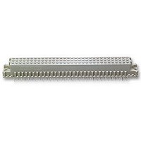
6. VISUAL AID
Figure 17 shows a typical application of a Eurocard Connector. This illustration should be used by production
personnel to ensure a correctly applied product. Applications which DO NOT appear correct should be
inspected using the information in the preceding pages of this specification and in the instructional material
shipped with the product.
18 of 18
PC BOARD MUST
NOT BE DAMAGED
HOUSING MUST
BE BOTTOMED
AGAINST PC BOARD
SHROUD OF PROPER SIZE
AND HEIGHT MUST BE
PLACED OVER CONTACTS
AND SEATED ON PC BOARD
BOARDLOCKS
MUST BE IN PLACE
THROUGH PC BOARD
CONTACTS MUST
BE STRAIGHT
AND UNDAMAGED
FIGURE 17. VISUAL AID
WIRE WRAP MUST
BE TIGHT AND
SECURE
PINS MUST BE STRAIGHT
AND UNDAMAGED
HARDWARE MUST BE
SECURELY FASTENED
SOLDER FILLETS
MUST BE FORMED
EVENLY AROUND
SOLDER TINES
114- 9014
Rev G
Related parts for 5535032-5
Image
Part Number
Description
Manufacturer
Datasheet
Request
R


Part Number:
Description:
Printers THERMAL PRINTER HS-SLEEVE MARKER
Manufacturer:
TE Connectivity

Part Number:
Description:
High Speed / Modular Connectors 30P HEADER ASSY
Manufacturer:
TE Connectivity
Datasheet:

Part Number:
Description:
High Speed / Modular Connectors REC 6X005P R/A LT B-PLANE HS3
Manufacturer:
TE Connectivity
Datasheet:

Part Number:
Description:
High Speed / Modular Connectors 2MM HM RCPT 50P R/A AU
Manufacturer:
TE Connectivity
Datasheet:

Part Number:
Description:
High Speed / Modular Connectors 2MM HM RCPT 50P R/A AU
Manufacturer:
TE Connectivity
Datasheet:


Part Number:
Description:
Manufacturer:
TE Connectivity
Datasheet:


Part Number:
Description:
Manufacturer:
TE Connectivity
Datasheet:

Part Number:
Description:
Manufacturer:
TE Connectivity
Datasheet:

Part Number:
Description:
Manufacturer:
TE Connectivity
Datasheet: