749808-9 TE Connectivity, 749808-9 Datasheet - Page 3
749808-9
Manufacturer Part Number
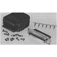
749808-9
Description
KIT,PLUG,15P,HDP-20
Manufacturer
TE Connectivity
Specifications of 749808-9
Rohs Compliant
YES
Product Type
Connector
Product Series
HDP-20 (Crimp Snap)
Termination Method To Wire/cable
Crimp Snap
Mating Connector Lock
With
Mating Connector Lock Type
Mounting Screws, Retainer Clip
Shell Size
2
Shell Type
Full Metal Shell
Grounding Indents
With
Grade
Standard
Cable Clamp Type
One-Piece Quick Snap
Grommets
Without
Screws And Retainer Clips
With
Body Material
Polypropylene
Shell Material
Steel
Retainer Clip Material
Stainless Steel
Strain Relief Clip Material
Stainless Steel
Screw Material
Steel
Cover Material
Polypropylene
Mounting Screw Material
Steel
Mounting Screw Plating
Zinc
Screw Plating
Zinc
Shielded
No
Solder Tail Contact Plating
Tin over Nickel
Number Of Positions
15
Wire Range (mm² [awg])
0.2 - 0.56 [24-20]
Cable Insulation Diameter (mm [in])
4.32 – 9.65 [0.170 – 0.380]
Cable Exit Angle
180°
Cable Gate Plug Material
Polypropylene
Shell Plating
Tin over Copper
Preloaded
Yes
Contact Type
Pin
Contact Base Material
Brass
Contact Plating, Mating Area, Material
Gold Flash
Contact Size
20
Enclosure
With
Connector Style
Plug
Housing Material
Nylon, Polyester GF
Ul Flammability Rating
UL 94V-0
Housing Color
Black
Rohs/elv Compliance
RoHS compliant, ELV compliant
Lead Free Solder Processes
Not relevant for lead free process
Rohs/elv Compliance History
Always was RoHS compliant
Packaging Method
Bulk
Packaging Quantity
100/Package
Available stocks
Company
Part Number
Manufacturer
Quantity
Price
Company:

Part Number:
749808-9
Manufacturer:
TE Connectivity AMP Connectors
Quantity:
457


Tem perature rise vs current.
Vibration, random .
Mechanical shock.
Durability.
Mating force.
Unm ating force.
Contact insertion force.
Rev F
Test Description
30°C m axim um tem perature rise at
specified current.
No discontinuities of 1 m icrosecond
or longer duration.
See Note.
No discontinuities of 1 m icrosecond
or longer duration.
See Note.
See Note.
Size Posn
Size Posn
13.3 N [3 lbf] m axim um per contact. EIA-364-5.
1
2
3
4
5
1
2
3
4
5
15
25
37
50
15
25
37
50
9
9
Figure 1 (continued)
MECHANICAL
Requirem ent
12.5 [2.8]
20.9 [4.7]
34.7 [7.8]
51.6 [11.6] 177.9 [40]
69.4 [15.6] 195.7 [44]
12.5 [2.8]
20.9 [4.7]
34.7 [7.8]
51.6 [11.6] 177.9 [40]
69.4 [15.6] 195.7 [44]
(N [lbf] m axim um )
W ithout
(N [lbf] m axim um )
W ithout
Ground Indents
Ground Indents
133.4 [30]
146.8 [33]
164.6 [37]
133.4 [30]
146.8 [33]
164.6 [37]
W ith
W ith
EIA-364-70, Method 1.
Stabilize at a single current level
until 3 readings at 5 m inute intervals
are within 1°C.
See Figure 4.
EIA-364-28, Test Condition V,
Condition F.
Subject m ated specim ens to 20.71
G's rm s between 50 to 2000 Hz.
Fifteen m inutes in each of 3
m utually perpendicular planes.
See Figure 5.
EIA-364-27, Method A.
Subject m ated specim ens to 50 G's
half-sine shock pulses of 11
m illiseconds duration. Three shocks
in each direction applied along 3
m utually perpendicular planes, 18
total shocks.
See Figure 5.
EIA-364-9.
Mate and unm ate gold flash
specim ens for 100 cycles, and 30
ìin gold specim ens for 500 cycles
at a m axim um rate of 200 cycles
per hour.
EIA-364-13.
Measure force necessary to m ate
specim ens at a m axim um rate of
25.4 m m [1 in] per m inute.
EIA-364-13.
Measure force necessary to unm ate
specim ens at a m axim um rate of
25.4 m m [1 in] per m inute.
Measure force necessary to insert
contact into housing.
Procedure
108-40005
3 of 10
Related parts for 749808-9
Image
Part Number
Description
Manufacturer
Datasheet
Request
R

Part Number:
Description:
Conn D-Subminiature PL 9 POS Crimp ST Cable Mount 9 Terminal 1 Port Bulk
Manufacturer:
TE Connectivity
Datasheet:
Part Number:
Description:
D SUB CONNECTOR, STANDARD, 9POS, PLUG
Manufacturer:
TE Connectivity
Part Number:
Description:
D SUB CONNECTOR, STANDARD, 25POS, PLUG
Manufacturer:
TE Connectivity

Part Number:
Description:
HDP-20 Backshell Kit, Crimp Snap-In Un-Shielded Plastic, 9 Positions, Plug Connector
Manufacturer:
TE Connectivity
Part Number:
Description:
HDP-20 Backshell Kit, Crimp Snap-In Un-Shielded Plastic, 25 Positions, Plug Connector
Manufacturer:
TE Connectivity

Part Number:
Description:
High Speed / Modular Connectors 30P HEADER ASSY
Manufacturer:
TE Connectivity
Datasheet:

Part Number:
Description:
High Speed / Modular Connectors REC 6X005P R/A LT B-PLANE HS3
Manufacturer:
TE Connectivity
Datasheet:

Part Number:
Description:
High Speed / Modular Connectors 2MM HM RCPT 50P R/A AU
Manufacturer:
TE Connectivity
Datasheet:

Part Number:
Description:
High Speed / Modular Connectors 2MM HM RCPT 50P R/A AU
Manufacturer:
TE Connectivity
Datasheet:


Part Number:
Description:
Manufacturer:
TE Connectivity
Datasheet:


Part Number:
Description:
Manufacturer:
TE Connectivity
Datasheet:

Part Number:
Description:
Manufacturer:
TE Connectivity
Datasheet:

Part Number:
Description:
Manufacturer:
TE Connectivity
Datasheet: