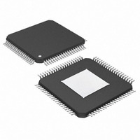
MAX105ECS+ Maxim Integrated Products, MAX105ECS+ Datasheet - Page 18

MAX105ECS+
Manufacturer Part Number
MAX105ECS+
Description
IC ADC 6BIT 800MSPS DL 80TQFP
Manufacturer
Maxim Integrated Products
Datasheet
1.MAX105ECS.pdf
(21 pages)
Specifications of MAX105ECS+
Number Of Bits
6
Sampling Rate (per Second)
800M
Data Interface
Parallel
Number Of Converters
2
Power Dissipation (max)
2.6W
Voltage Supply Source
Analog and Digital
Operating Temperature
-40°C ~ 85°C
Mounting Type
Surface Mount
Package / Case
80-TQFP Exposed Pad, 80-eTQFP, 80-HTQFP, 80-VQFP
Number Of Adc Inputs
2
Conversion Rate
800 MSPs
Resolution
6 bit
Snr
37 dB
Voltage Reference
2.5 V
Supply Voltage (max)
3.6 V
Supply Voltage (min)
3 V
Maximum Power Dissipation
3.5 W
Maximum Operating Temperature
+ 85 C
Mounting Style
SMD/SMT
Input Voltage
3.3 V
Minimum Operating Temperature
- 40 C
Lead Free Status / RoHS Status
Lead free / RoHS Compliant
age, the data converter die is attached to an exposed
pad (EP) leadframe using a thermally conductive
epoxy. The package is molded in a way, that this lead-
frame is exposed at the surface, facing the printed cir-
cuit board (PC board) side of the package (Figure 10).
This allows the package to be attached to the PC board
with standard infrared (IR) flow soldering techniques. A
specially created land pattern on the PC board, match-
ing the size of the EP (7.5mm x 7.5mm) does not only
guarantee proper attachment of the chip, but can also
be used for heat-sinking purposes. Designing thermal
vias* into the land area and implementing large ground
planes in the PC board design, further enhance the
thermal conductivity between board and package. To
remove heat from an 80-pin TQFP package efficiently,
an array of 6 x 6 vias (≤ 0.3mm diameter per via hole
and 1.2mm pitch between via holes) is required.
Note: Efficient thermal management for the MAX105 is
strongly depending on PC board and circuit design,
component placement, and installation. Therefore,
exact performance figures cannot be provided.
However, the MAX105EV kit exhibits a typical θja of
18°C/W. For more information on proper design tech-
niques and recommendations to enhance the thermal
performance of parts such as the MAX105, please refer
to Amkor Technology’s website at www.amkor.com.
Dual, 6-Bit, 800Msps ADC with On-Chip,
Wideband Input Amplifier
Figure 10. MAX105 Exposed Pad Package Cross-Section
*Connects the land pattern to internal or external copper planes.
18
TOP LAYER
GROUND PLANE
AGND, DGND
POWER PLANE
GROUND PLANE (AGND)
______________________________________________________________________________________
COPPER TRACE, 1oz.
6 x 6 ARRAY OF THERMAL VIAS
THERMAL LAND
COPPER PLANE, 1oz.
DIE
THERMAL LAND
COPPER PLANE, 1oz.
Integral nonlinearity is the deviation of the values on an
actual transfer function from a straight line. This straight
line is drawn between the endpoints of the transfer
function, once offset and gain errors have been nulli-
fied. The static linearity parameters for the MAX105 are
measured using the sine-histogram method.
Differential nonlinearity is the difference between an
actual step-width and the ideal value of 1LSB. A DNL
error specification of greater than -1LSB guarantees no
missing codes and a monotonic transfer function.
Aperture uncertainties affect the dynamic performance
of high-speed converters. Aperture jitter, in particular,
directly influences SNR and limits the maximum slew
rate (dV/dt) that can be digitized without significant
error. Aperture jitter limits the SNR performance of the
ADC, according to the following relationship:
where f
t
AJ
is the RMS aperture jitter. The MAX105’s innovative
SNR
Dynamic Parameter Definitions
IN
dB
Static Parameter Definitions
represents the analog input frequency and
= 20 x log
Differential Nonlinearity (DNL)
80-PIN TQFP PACKAGE
WITH EXPOSED PAD
Integral Nonlinearity (INL)
10
Aperture Jitter and Delay
[1 / (2 x π x f
MAX105
BONDING WIRE
EXPOXY
EXPOSED PAD
IN
x t
AJ[RMS]
COPPER
TRACE, 1oz.
PC BOARD
)],


