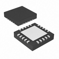
AR1020-I/ML Microchip Technology, AR1020-I/ML Datasheet - Page 20

AR1020-I/ML
Manufacturer Part Number
AR1020-I/ML
Description
IC TOUCH SCREEN CTRLR 20-QFN
Manufacturer
Microchip Technology
Type
Resistiver
Specifications of AR1020-I/ML
Resolution (bits)
10 b
Touch Panel Interface
4-Wire, 5-Wire, 8-Wire
Number Of Inputs/keys
3 Key
Data Interface
I²C, Serial, SPI™
Voltage - Supply
3.3 V ~ 5.5 V
Current - Supply
17mA
Operating Temperature
-40°C ~ 85°C
Mounting Type
Surface Mount
Package / Case
20-VQFN Exposed Pad, 20-HVQFN, 20-SQFN, 20-DHVQFN
Voltage Supply Source
Single Supply
Controller Type
Touch Screen
Ic Interface Type
I2C, SPI
Supply Voltage Range
3.3V To 5V
Operating Temperature Range
-40°C To +85°C
Digital Ic Case Style
QFN
No. Of Pins
20
Lead Free Status / RoHS Status
Lead free / RoHS Compliant
Sampling Rate (per Second)
-
Lead Free Status / RoHS Status
Lead free / RoHS Compliant, Lead free / RoHS Compliant
Available stocks
Company
Part Number
Manufacturer
Quantity
Price
Company:
Part Number:
AR1020-I/ML
Manufacturer:
MICROCHIP
Quantity:
3 400
Company:
Part Number:
AR1020-I/ML
Manufacturer:
MCP
Quantity:
5 056
Part Number:
AR1020-I/ML
Manufacturer:
MIC
Quantity:
20 000
7.12.11 TouchOptions Register (offset 0x0D)
The TouchOptions register contains various “touch” related option bits.
R = Readable bit, W = Writable bit, U = Unimplemented bit read as ‘0’
Bit 7
bit 7-2 Unimplemented: Read as ‘0’
bit 1
bit 0
7.12.12 CalibrationInset Register (offset 0x0E)
The CalibrationInset register defines the expected position of the calibration points, inset from the perimeter of the
touch sensor’s active area, by a percentage of the full scale dimension.
This allows for the calibration targets to be placed inset from edge to make it easier for a user to touch them.
The CalibrationInset register value is only used when the Calibration Mode command is issued to the controller.
In Calibration Mode, the controller will extrapolate the calibration point touch report values by the defined
CalibrationInset percentage to achieve full scale.
A software application that issues the Calibration Mode command must present the displayed calibration targets
at the same inset percentage as defined in this CalibrationInset register.
Valid values are as follows.
0 ≤ CalibrationInset ≤ 40
Calibration Inset = ( CalibrationInset / 2 ) % , Range of 0–20% with 0.5% resolution
For example, CalibrationInset = 25 (0x19) yields a calibration inset of (25 / 2) or 12.5%. During the calibration
procedure, the controller will internally extrapolate the calibration point touch values in Calibration Mode by 12.5%
to achieve full scale.
DS41393A-Page 16
A 4-wire touch sensor will not work if the 48W configuration bit is incorrectly defined as one, which
selects 8-wire.
An 8-wire touch sensor will provide basic operation if the 48W configuration bit is incorrectly defined
as zero, which selects 4-wire. However, the benefit of the 8-wire sensor will only be realized, if the
48W configuration bit is correctly defined as one, selecting 8-wire.
U–0
–
48W: 4-wire or 8-wire Sensor Selection bit
1 = Selects 8-wire sensor operating mode
0 = Selects 4-wire sensor operating mode
CCE: Calibrated Coordinates Enable bit
1 = Enables calibrated coordinates, if the controller has been calibrated
0 = Disables calibrated coordinates
Location of calibration
targets presented
during calibration.
U–0
–
12.5% of
Full Scale
U–0
–
12.5% of
Full Scale
U–0
–
U–0
–
U–0
–
48W
R/W
© 2009 Microchip Technology, Inc.
CCE
R/W
Bit 0


