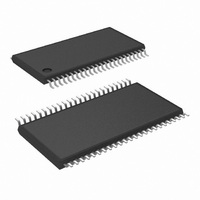
LM8300IMT9B/NOPB National Semiconductor, LM8300IMT9B/NOPB Datasheet - Page 17

LM8300IMT9B/NOPB
Manufacturer Part Number
LM8300IMT9B/NOPB
Description
IC TOUCHSCREEN CTLR 48-TSSOP
Manufacturer
National Semiconductor
Type
Resistiver
Datasheet
1.LM8500IMT9BNOPB.pdf
(20 pages)
Specifications of LM8300IMT9B/NOPB
Touch Panel Interface
4-Wire
Number Of Inputs/keys
1 TSC
Resolution (bits)
10 b
Data Interface
UART
Data Rate/sampling Rate (sps, Bps)
38.4k
Voltage - Supply
2.7 V ~ 5.5 V
Current - Supply
11.5mA
Operating Temperature
0°C ~ 70°C
Mounting Type
Surface Mount
Package / Case
48-TSSOP
Voltage Supply Source
Single Supply
For Use With
LM8300-REF-01 - BOARD EVALUATION LM8300
Lead Free Status / RoHS Status
Lead free / RoHS Compliant
Sampling Rate (per Second)
-
Other names
LM8300IMT9B
Available stocks
Company
Part Number
Manufacturer
Quantity
Price
Company:
Part Number:
LM8300IMT9B/NOPB
Manufacturer:
NS/TI
Quantity:
8
14.0 Calibration
14.2 CALIBRATION PROCEDURES WITH
COORDINATES CHECKING ENABLED
To do TS calibration with coordinates checking enabled, first
ensure the Calibration Coordinates Checking is enabled on
the device. This can be accomplished by sending a com-
mand byte of $B1 (Read Parameters command) and check-
ing the 5th bit of the 12th reply byte is set. Alternatively, if the
device is set to Calibration Coordinates Checking enabled
as default, this step can be skipped.
The TS driver sends the command byte to do calibration
($BD). The TS driver should wait for the reply bytes and
ensure it is the same command bytes it sent. The device
waits for a touch to be detected on the panel. Once a touch
is detected, the device checks it against the predetermined
FIGURE 8. Calibration Procedures with Coordinates Checking Enabled
(Continued)
17
calibration values as noted on Table 3. Two Points Calibra-
tion, Table 4. Five Points Calibration , and Table 5. Thirteen
Points Calibration. If the detected touch is within the pre-
defined value (
send a command of $C4 to the TS driver and store the
calibration point in the internal flash. The TS driver can now
send a command byte to do the next calibration point. If the
detected touch is not within the predefined value, the device
will send a reply byte of $C8 to the TS driver. Upon receiving
this reply byte, the TS driver can resend the calibration
command for the same calibration point, go the next calibra-
tion point, or abort the calibration process.
Once all the calibration points are done, the device does a
self-test. If the self-test was not successful, the device will
±
127 of the raw A/D value), the device will
20037210
www.national.com


