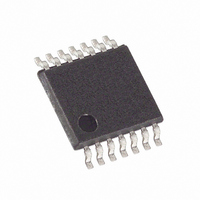
DS1805E-010+ Maxim Integrated Products, DS1805E-010+ Datasheet - Page 7

DS1805E-010+
Manufacturer Part Number
DS1805E-010+
Description
IC POT DIG ADDRESS 10K 14-TSSOP
Manufacturer
Maxim Integrated Products
Datasheet
1.DS1805E-010.pdf
(10 pages)
Specifications of DS1805E-010+
Taps
256
Resistance (ohms)
10K
Number Of Circuits
1
Temperature Coefficient
750 ppm/°C Typical
Memory Type
Volatile
Interface
I²C, 2-Wire Serial
Voltage - Supply
2.7 V ~ 5.5 V
Operating Temperature
-40°C ~ 85°C
Mounting Type
Surface Mount
Package / Case
14-TSSOP
Resistance In Ohms
10K
Lead Free Status / RoHS Status
Lead free / RoHS Compliant
Figure 2. 2-Wire Data Transfer Overview
The potentiometer is composed of a 256-position resis-
tor array. Two 8-bit registers are provided to ensure
compatibility with DS1803-based designs. Register-0 is
a general-purpose SRAM byte, while register-1 is
assigned to the potentiometer and is used to set the
wiper position on the resistor array. The wiper terminal
is multiplexed to one of 256 positions on the resistor array
based on its corresponding 8-bit register value. The high-
est wiper setting, FFh, is 1 LSB away from H1 (resistor
255), while the lowest setting, 00h, connects to L1.
The DS1805 is a volatile device that does not maintain
the position of the wiper during power-down or loss of
power. On power-up, the wiper position is set to 00h
(the low-end terminal). The user can then set the wiper
value to a desired position.
Communication with the DS1805 takes place over the
2-wire serial interface consisting of the bidirectional
data terminal, SDA, and the serial clock input, SCL.
Complete details of the 2-wire interface are discussed
in the 2-Wire Serial Data Bus section.
The 2-wire interface and address inputs A0, A1, and A2
allow operation of up to eight devices in a bus topology,
with A0, A1, and A2 being the address of the device.
The DS1805 is offered in three standard resistor values:
10kΩ, 50kΩ, and 100kΩ. The resolution of the poten-
tiometer is defined as R
resistor value of the potentiometer. The DS1805 is
designed to operate using 3V or 5V power supplies over
SDA
SCL
CONDITION
START
MSB
Application Considerations
1
TOT
2
/256, where R
SLAVE ADDRESS
Addressable Digital Potentiometer
_____________________________________________________________________
6
TOT
7
is the total
DIRECTION
R/W
BIT
8
SIGNAL FROM RECEIVER
ACKNOWLEDGEMENT
ACK
9
the industrial (-40°C to +85°C) temperature range.
Maximum input signal levels across the potentiometer
cannot exceed the operating power supply of the device.
The DS1805 supports a bidirectional 2-wire bus and
data transmission protocol. A device that sends data on
the bus is called a transmitter, and a device receiving
data is called a receiver. The device that controls the
message is called a master. The devices that are con-
trolled by the master are slaves. The bus must be con-
trolled by a master device that generates the serial
clock (SCL), controls the bus access, and generates the
START and STOP conditions. The DS1805 operates as
a slave on the 2-wire bus. Connections to the bus are
made through the open-drain I/O lines, SDA and SCL.
The following bus protocol has been defined (Figure 2):
•
•
Accordingly, the following bus conditions have been
defined:
Bus not busy: Both data and clock lines remain high.
Start data transfer: A change in the state of the data
line from high to low while the clock is high defines a
START condition.
Data transfer can be initiated only when the bus is
not busy.
During data transfer, the data line must remain sta-
ble whenever the clock line is high. Changes in the
data line while the clock line is high will be interpret-
ed as control signals.
1
2
REPEATED IF MORE BYTES
ARE TRANSFERED
2-Wire Serial Data Bus
3–7
SIGNAL FROM RECEIVER
ACKNOWLEDGEMENT
8
ACK
9
OR REPEATED
CONDITION
CONDITION
START
STOP
7


