V23072C1062A303 TE Connectivity, V23072C1062A303 Datasheet - Page 4
V23072C1062A303
Manufacturer Part Number
V23072C1062A303
Description
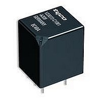
SIGNAL RELAY, SPDT-CO, 24VDC, 10A, THD
Manufacturer
TE Connectivity
Datasheet
1.V23072C1062A303.pdf
(6 pages)
Specifications of V23072C1062A303
Coil Voltage Vdc Nom
24V
Contact Current Max
15A
Coil Resistance
520ohm
Contact Configuration
SPDT
Relay Mounting
PCB
External Height
19.2mm
External Width
14.7mm
External Depth
16.9mm
Rohs Compliant
Yes
Contact Form
1 Form C, 1 C/O
Coil Voltage
24 VDC
Mounting Style
PCB
Power Consumption
1.1 W
Contact Material
Fine Grained Silver (AgNi0.15)
Lead Free Status / Rohs Status
Details
Available stocks
Company
Part Number
Manufacturer
Quantity
Price


Load limit curve
Contact data
Typical areas of application
Contact configuration
Circuit symbol
(see also Pin assignment)
Rated voltage
Rated current at 85 °C
Contact material
Max. switching voltage/power
Max. switching current
On
Off
Min. recommended load
Voltage drop at 10 A (initial)
for NC/NO contacts
Mechanical endurance (without load)
Electrical endurance
(example of resistive load)
1)
2)
3)
4)
5)
Pin assignment (open and sealed)
1 make contact/
1 form A
See chapter Diagnostics in our Application Recommendations on page 18.
The values apply to a resistive load or inductive load with suitable spark suppression.
For a load current duration of maximum 3 s for a make/break ratio of 1:10.
Corresponds to the peak inrush current on initial actuation (cold filament).
At 50 % ON period
2)
1)
5)
PCB relays
Single relays
Mini power relay K (open and sealed)
1 double make contact/
1 form U
contact/
Form A
Make
10 A
60 A
20 A
Typ. 50 mV, 300 mV max.
Changeover
12 A/60 A
10 A/20 A
5 A/10 A
contact/
Tyco0626-Y
Form C
NC/NO
Load limit
curve 1
Load limit
curve 2
Load limit
curve 3
3
Tyco
Load limi
curve 1
Load limi
curve 2
Load limi
curve 3
Please observe the disclaimer.
4
Resistive / inductive loads
> 2 x 10
5
10 A, 13.5 V
AgNi0.15
5
operations
1 changeover contact/
1 form C
Load limit curve 1
connected as form X, load on pin 5
and 7
Load limit curve 2
no stationary arc / make contact
Load limit curve 3
during transit time (changeover contact)
Typ. 2 x 50 mV, 300 mV max.
See load limit curve
> 10
make contact/
1 A at 5 V
2 x 40 A
2 x 20 A
Double
Form U
2 x 6 A
7
12 V
operations
^
= safe shutdown,
^
= safe shutdown,
^
= arc extinguishes
up to 3 x 21 W
> 1,5 x 10
operations
contact/
Form A
60 A
Make
5 A
6 A
Typ. 150 mV, 300 mV max.
3)
Indicator lamps
6
AgSnO
Catalog 1308028
2
up to 6 x 21 W
make contact/
> 1.5 x 10
operations
Form U
2 x 5 A
120 A
Issued 01-05
Double
12 A
3)
6
103
Related parts for V23072C1062A303
Image
Part Number
Description
Manufacturer
Datasheet
Request
R

Part Number:
Description:
PCB relays Single relays Mini power relay K (open and sealed)
Manufacturer:
MACOM [Tyco Electronics]
Datasheet:

Part Number:
Description:
Printers THERMAL PRINTER HS-SLEEVE MARKER
Manufacturer:
TE Connectivity


Part Number:
Description:
Manufacturer:
TE Connectivity
Datasheet:


Part Number:
Description:
Manufacturer:
TE Connectivity
Datasheet:

Part Number:
Description:
Manufacturer:
TE Connectivity
Datasheet: