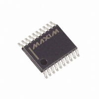
DS1846E-010+T&R Maxim Integrated Products, DS1846E-010+T&R Datasheet - Page 9

DS1846E-010+T&R
Manufacturer Part Number
DS1846E-010+T&R
Description
IC NV TRI-POT MEM MON 20TSSOP
Manufacturer
Maxim Integrated Products
Datasheet
1.DS1846E-010.pdf
(18 pages)
Specifications of DS1846E-010+T&R
Taps
100, 256
Resistance (ohms)
10K, 100K
Number Of Circuits
3
Temperature Coefficient
750 ppm/°C Typical
Memory Type
Non-Volatile
Interface
2-Wire Serial
Voltage - Supply
4.5 V ~ 5.5 V
Operating Temperature
-40°C ~ 85°C
Mounting Type
Surface Mount
Package / Case
20-TSSOP
Resistance In Ohms
10K, 100K
Lead Free Status / RoHS Status
Lead free / RoHS Compliant
DS1846
WRITE PROTECT
The WP pin protects EEPROM data and potentiometer position from alteration in an application. This pin
must be open or connected high to protect data from alteration. WP has an internal pullup (R
).
WP
READING AND WRITING THE POTENTIOMETER VALUES
Reading from and writing to the potentiometers consists of a standard read or write to EEPROM memory
at the addresses F8h, F9h, and FAh. The 8-bit value at address F8h controls the wiper setting for
potentiometer 1, which has 256 positions. The 8-bit value at addresses F9h and FAh control the wiper
setting of potentiometer 0 and 2, respectively; each has 100 positions. Potentiometer 1 may be set to any
value between 00h and FFh. A value of 00h sets the wiper of potentiometer 1 to its lowest value and FFh
sets the wiper to its highest. Potentiometer 0 or 2 may be set to any value between 00h and 63h. A value
of 00h sets the wiper of potentiometer 0 or 2 to its lowest position and 63h sets the wiper to its highest
position. Any hexadecimal value is a valid address. Writing a value greater than 63h will set the
potentiometer according to the seven LSBs and the MSB is ignored.
2- WIRE DATA TRANSFER PROTOCOL Figure 2
2-WIRE AC CHARACTERISTICS Figure 3
9 of 18


