2-1462051-2 TE Connectivity, 2-1462051-2 Datasheet
2-1462051-2
Specifications of 2-1462051-2


Related parts for 2-1462051-2


2-1462051-2 Summary of contents
Page 1
... U nominal coil voltage nom. 1 0.5 U op. min. 0 -55 -45 -35 -25 - 105 115 125 135 Ambient Temperature [°C] Datasheets, product data, ‘Definitions’ sec- tion, application notes and all specifications are subject to change. Axicom Latching type, 1 coil rest condition Sep 140 mW Coil ...
Page 2
... Category of environmental protection -0.03dB / -0.12dB / -0.30dB -0.03dB / -0.12dB / -0.30dB 50 50 1.05 / 1.10 / 1.25 1.05 / 1.10 / 1.25 Degree of protection, IEC 60529 -95dB / -80dB / -55dB -95dB / -80dB / -55dB Vibration resistance (functional) Shock resistance (functional), half sinus 11ms -0.03dB / -0.12dB / -0.30dB -0 ...
Page 3
... Rev. 0910 Datasheets and product specification ac- cording to IEC 61810-1 and to be used only www.tycoelectronics.com together with the ‘Definitions’ section. © 2010 Tyco Electronics Ltd. (Continued) Bistable, 1 coil Contacts are shown in reset condition. Contact position might change during transportation and must be reset before use ...
Page 4
... Reel dimensions Time [s] Time [s] Datasheets and product data is subject to the terms of the disclaimer and all chapters of the ‘Definitions’ section, available at http://relays.tycoelectronics.com/definitions Axicom Tape and reel for SMT Datasheets, product data, ‘Definitions’ sec- tion, application notes and all specifications ...
Page 5
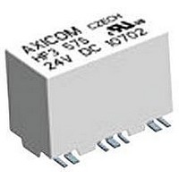
... Axicom HF3 53 S Typical product code Coil type Part number Monostable 3-1462051-0 2-1462051-8 2-1462051-3 3-1462051-1 2-1462051-2 Bistable 1 coil 2-1462051-7 Bistable 2 coils 3-1462051-2 2-1462051-5 2-1462051-4 2-1462051-6 Monostable 3-1462050-0 3-1462050-1 3-1462050-2 3-1462050-3 3-1462050-7 Bistable 2 coils ...