DAC08EPZ Analog Devices Inc, DAC08EPZ Datasheet - Page 10
DAC08EPZ
Manufacturer Part Number
DAC08EPZ
Description
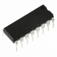
IC DAC 8BIT MULTIPLY HS 16-DIP
Manufacturer
Analog Devices Inc
Specifications of DAC08EPZ
Data Interface
Parallel
Settling Time
85ns
Number Of Bits
8
Number Of Converters
1
Voltage Supply Source
Dual ±
Power Dissipation (max)
174mW
Operating Temperature
0°C ~ 70°C
Mounting Type
Through Hole
Package / Case
16-DIP (0.300", 7.62mm)
Resolution (bits)
8bit
Sampling Rate
11.8MSPS
Input Channel Type
Parallel
Supply Current
-6.5mA
Digital Ic Case Style
DIP
No. Of Pins
16
Number Of Channels
1
Resolution
8b
Interface Type
Parallel
Single Supply Voltage (typ)
Not RequiredV
Dual Supply Voltage (typ)
±15V
Architecture
Current Steering
Power Supply Requirement
Dual
Output Type
Current
Single Supply Voltage (min)
Not RequiredV
Single Supply Voltage (max)
Not RequiredV
Dual Supply Voltage (min)
±4.5V
Dual Supply Voltage (max)
±18V
Operating Temp Range
0C to 70C
Operating Temperature Classification
Commercial
Mounting
Through Hole
Pin Count
16
Package Type
PDIP
Supply Voltage Range - Analog
± 4.5V To ± 18V
Rohs Compliant
Yes
Lead Free Status / RoHS Status
Lead free / RoHS Compliant
Lead Free Status / RoHS Status
Lead free / RoHS Compliant, Lead free / RoHS Compliant
Available stocks
Company
Part Number
Manufacturer
Quantity
Price
Company:

Part Number:
DAC08EPZ
Manufacturer:
PHI
Quantity:
6 224


DAC08
APPLICATION INFORMATION
REFERENCE AMPLIFIER SETUP
The DAC08 is a multiplying D/A converter in which the output
current is the product of a digital number and the input refer-
ence current. The reference current may be fixed or may vary
from nearly zero to 4.0 mA. The full-scale output current is a
linear function of the reference current and is given by:
In positive reference applications, an external positive reference
voltage forces current through R14 into the V
(Pin 14) of the reference amplifier. Alternatively, a negative
reference may be applied to V
flows from ground through R14 into V
reference case. This negative reference connection has the advan-
tage of a very high impedance presented at Pin 15. The voltage
at Pin 14 is equal to and tracks the voltage at Pin 15 due to the
high gain of the internal reference amplifier. R15 (nominally equal
to R14) is used to cancel bias current errors; R15 may be elimi-
nated with only a minor increase in error.
Bipolar references may be accommodated by offsetting V
Pin 15. The negative common-mode range of the reference
amplifier is given by: V
The positive common-mode range is V+ less 1.5 V.
When a dc reference is used, a reference bypass capacitor is
recommended. A 5.0 V TTL logic supply is not recommended
as a reference. If a regulated power supply is used as a reference,
R14 should be split into two resistors with the junction bypassed to
ground with a 0.1 µF capacitor.
For most applications the tight relationship between I
will eliminate the need for trimming I
trimming may be accomplished by adjusting the value of R14, or
by using a potentiometer for R14. An improved method of
full-scale trimming which eliminates potentiometer T.C. effects
is shown in the recommended full-scale adjustment circuit.
Using lower values of reference current reduces negative power
supply current and increases reference amplifier negative com-
mon-mode range. The recommended range for operation with
a dc reference current is 0.2 mA to 4.0 mA.
REFERENCE AMPLIFIER COMPENSATION FOR
MULTIPLYING APPLICATIONS
AC reference applications will require the reference amplifier to
be compensated using a capacitor from Pin 16 to V–. The value
of this capacitor depends on the impedance presented to Pin 14:
for R14 values of 1.0, 2.5 and 5.0 kΩ, minimum values of C
are 15, 37 and 75 pF. Larger values of R14 require proportion-
ately increased values of C
ratio of C
For fastest response to a pulse, low values of R14 enabling
small C
impedance such as a transistor current source, none of the
above values will suffice and the amplifier must be heavily
compensated which will decrease overall bandwidth and slew
rate. For R14 = 1 kΩ and C
slews at 4 mA/µs enabling a transition from I
2 mA in 500 ns.
Operation with pulse inputs to the reference amplifier may be
accommodated by an alternate compensation scheme. This
C
C
values should be used. If Pin 14 is driven by a high
(pF) to R14 (kΩ) = 15.
I
FR
=
255
256
CM
– = V– plus (I
×
C
I
for proper phase margin, so the
REF
C
REF(–)
= 15 pF, the reference amplifier
, where I
at Pin 15; reference current
REF
REF
REF(+)
. If required, full-scale
REF
× 1 kΩ) plus 2.5 V.
= I
as in the positive
REF
REF(+)
14
= 0 to I
REF
terminal
and I
REF
REF
C
or
FS
=
technique provides lowest full-scale transition times. An internal
clamp allows quick recovery of the reference amplifier from a
cutoff (I
occurs in 120 ns when the equivalent impedance at Pin 14 is
200 Ω and C
which is relatively independent of R
LOGIC INPUTS
The DAC08 design incorporates a unique logic input circuit
that enables direct interface to all popular logic families and
provides maximum noise immunity. This feature is made pos-
sible by the large input swing capability, 2 µA logic input
current and completely adjustable logic threshold voltage.
For V– = –15 V, the logic inputs may swing between –10 V
and +18 V. This enables direct interface with 15 V CMOS
logic, even when the DAC08 is powered from a 5 V supply.
Minimum input logic swing and minimum logic threshold
voltage are given by: V– plus (I
logic threshold may be adjusted over a wide range by placing
an appropriate voltage at the logic threshold control pin (Pin 1,
V
V
1.4 above V
1. When interfacing ECL, an I
interfacing other logic families, see preceding page. For general
set-up of the logic control circuit, it should be noted that Pin 1
will source 100 µA typical; external circuitry should be designed
to accommodate this current.
Fastest settling times are obtained when Pin 1 sees a low imped-
ance. If Pin 1 is connected to a 1 kΩ divider, for example, it
should be bypassed to ground by a 0.01 µF capacitor.
ANALOG OUTPUT CURRENTS
Both true and complemented output sink currents are provided
where I
when a “1” (logic high) is applied to each logic input. As the
binary count increases, the sink current at pin 4 increases pro-
portionally, in the fashion of a “positive logic” D/A converter.
When a “0” is applied to any input bit, that current is turned
off at Pin 4 and turned on at Pin 2. A decreasing logic count
increases
Both outputs may be used simultaneously. If one of the outputs
is not required, it must be connected to ground or to a point
capable of sourcing I
Both outputs have an extremely wide voltage compliance enabling
fast direct current-to-voltage conversion through a resistor tied
to ground or other voltage source. Positive compliance is 36 V
above V– and is independent of the positive supply. Negative
compliance is given by V– plus (I
The dual outputs enable double the usual peak-to-peak load
swing when driving loads in quasi-differential fashion. This
feature is especially useful in cable driving, CRT deflection and
in other balanced applications such as driving center-tapped
coils and transformers.
POWER SUPPLIES
The DAC08 operates over a wide range of power supply voltages
from a total supply of 9 V to 36 V. When operating at supplies
of ± 5 V or less, I
current operation decreases power consumption and increases
negative compliance, reference amplifier negative common-mode
LC
LC
). The appropriate graph shows the relationship between
and V
O
REF
+
I
TH
O
I
= 0) condition. Full-scale transition (0 mA to 2 mA)
LC
O
C
as in a negative or inverted logic D/A converter.
over the temperature range, with V
. For TTL and DTL interface, simply ground pin
= I
= 0. This yields a reference slew rate of 16 mA/µs,
REF
FS
. Current appears at the “true” (I
FS
≤ 1 mA is recommended. Low reference
; do not leave an unused output pin open.
REF
REF
REF
= 1 mA is recommended. For
× 1 kΩ) plus 2.5 V.
IN
× 1 kΩ) plus 2.5 V. The
and V
IN
values.
TH
nominally
O
) output
Related parts for DAC08EPZ
Image
Part Number
Description
Manufacturer
Datasheet
Request
R

Part Number:
Description:
Manufacturer:
ON Semiconductor
Datasheet:

Part Number:
Description:
DAC (D/A Converters) IC DAC 4CH I2C ADJ justable Sink-Source
Manufacturer:
Maxim Integrated Products
Datasheet:
Part Number:
Description:
DAC (D/A Converters) IC DAC 2CH I2C ADJ justable Sink-Source
Manufacturer:
Maxim Integrated Products
Datasheet:

Part Number:
Description:
DAC (D/A Converters) 12-Bit Precision DAC
Manufacturer:
Maxim Integrated Products
Datasheet:
Part Number:
Description:
DAC (D/A Converters) 8-Bit Precision DAC
Manufacturer:
Maxim Integrated Products
Datasheet:
Part Number:
Description:
DAC (D/A Converters) 12-Bit Precision DAC
Manufacturer:
Maxim Integrated Products
Datasheet:
Part Number:
Description:
DAC (D/A Converters) 8-Bit Precision DAC
Manufacturer:
Maxim Integrated Products
Datasheet:
Part Number:
Description:
DAC (D/A Converters) 8-Bit Precision DAC
Manufacturer:
Maxim Integrated Products
Datasheet:
Part Number:
Description:
DAC (D/A Converters) 8-Bit 2Ch Precision DAC
Manufacturer:
Maxim Integrated Products
Datasheet:
Part Number:
Description:
DAC (D/A Converters) 8-Bit 2Ch Precision DAC
Manufacturer:
Maxim Integrated Products
Datasheet:
Part Number:
Description:
DAC (D/A Converters) 12-Bit 2Ch Precision DAC
Manufacturer:
Maxim Integrated Products
Datasheet:
Part Number:
Description:
DAC (D/A Converters) 8-Bit 2Ch Precision DAC
Manufacturer:
Maxim Integrated Products
Datasheet:
Part Number:
Description:
DAC (D/A Converters) 8-Bit 2Ch Precision DAC
Manufacturer:
Maxim Integrated Products
Datasheet:
Part Number:
Description:
DAC (D/A Converters) 12-Bit 2Ch Precision DAC
Manufacturer:
Maxim Integrated Products
Datasheet:
Part Number:
Description:
DAC (D/A Converters) 14-Bit Precision DAC
Manufacturer:
Maxim Integrated Products
Datasheet: