2007262-1 TE Connectivity, 2007262-1 Datasheet - Page 3
2007262-1
Manufacturer Part Number
2007262-1
Description
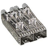
SFP+ Connector Cage
Manufacturer
TE Connectivity
Specifications of 2007262-1
Accessory Type
Connector Cage / Frame
Rohs Compliant
Yes
Product Type
Cage
Termination Type
Press-Fit
Configuration
1 x 2
Pcb Mount
Double Sided (Belly-to-Belly)
Termination Post Length (mm [in])
2.05 [0.081]
Cage Type
Ganged
Cage Material
Nickel Silver
Emi Containment
External Springs
Lightpipe
With
Rohs/elv Compliance
RoHS compliant, ELV compliant
Lead Free Solder Processes
Not relevant for lead free process
Rohs/elv Compliance History
Always was RoHS compliant
Application
SFP+
Packaging Method
Tray
For Use With
Small Form-Factor Pluggable Connectors
Available stocks
Company
Part Number
Manufacturer
Quantity
Price
Company:

Part Number:
2007262-1
Manufacturer:
TE/AMP
Quantity:
30 000
Company:
Part Number:
2007262-1
Manufacturer:
TE
Quantity:
20 000


Transceiver insertion force, SFP+
m odule to PCB connector and
SFP+ cage.
Transceiver extraction force, SFP+
m odule from PCB connector and
SFP+ cage.
Cage latch strength.
Cage press fit insertion force.
Cage press fit extraction force.
Rotational cable pull.
Cable retention force.
Cable side load force.
Cable longitudinal force.
Rev C
Test Description
33.4 N [7.5 lbf] m inim um .
34 N [7.64 lbf] m axim um without
heat sink and clip.
45.37 N [10.2 lbf] m axim um with
heat sink and clip.
See Note.
12.5 N [2.8 lbf] m axim um without
heat sink and clip.
14.36 N [3.23 lbf] m axim um with
heat sink and clip.
See Note.
91.2 N [20.5 lbf] m inim um .
See Note.
44.5 N [10 lbf] m axim um for single
port cage.
54.3 N [12.2 lbf] m axim um for
ganged cage.
See Note.
8.9 N [2.0 lbf] m inim um for single
port cage.
8.9 N [2.0 lbf] m inim um for ganged
cage.
See Note.
See Note.
No discontinuities of 1 m icrosecond
or longer duration.
Shall rem ain m ated.
See Note.
No discontinuities of 1 m icrosecond
or longer duration.
Shall rem ain m ated.
See Note.
No discontinuities of 1 m icrosecond
or longer duration.
Shall rem ain m ated.
See Note.
Figure 1 (continued)
Requirem ent
EIA-364-13.
Measure force necessary to insert
m odule into connector and cage at
a m axim um rate of 12.7 m m [.5 in]
per m inute.
EIA-364-13.
Measure force necessary to extract
m odule from connector and cage at
a m axim um rate of 12.7 m m [.5 in]
per m inute.
EIA 364-98.
Apply specified axial load to latch at
a m axim um rate of 12.7m m [.5 in]
per m inute and hold for 1 m inute to
verify cage latch strength.
EIA-364-5.
Measure force necessary to push
the cage into the host board at a
m axim um rate of 12.7 m m [.5 in]
per m inute.
EIA-364-5.
Measure force necessary to push
the cage out of the host board by
applying specified force in a vertical
direction at a m axim um rate of 12.7
m m [.5 in] per m inute.
Load cable m odule into a cage
assem bly m ounted to a test board,
with attached bezel. Apply axial load
at a m axim um rate of 12.7 m m [.5
in] per m inute, rotate cable 40
degrees toward printed circuit
board, and then rotate 360 degrees
with the load still applied.
EIA-364-98.
Apply a force of 80 N [18 lbf] in an
axial direction and hold for 10
m inutes.
EIA-364-38.
Apply a force of 80 N [18 lbf] to the
cable plug in a plane parallel to the
bezel and hold for 10 m inutes.
EIA-364-38.
Apply a force of 100 N [22.5 lbf] to
the cable plug in a plane
perpendicular to the bezel and hold
for 10 m inutes.
Procedure
108-2364
3 of 6
Related parts for 2007262-1
Image
Part Number
Description
Manufacturer
Datasheet
Request
R

Part Number:
Description:
Printers THERMAL PRINTER HS-SLEEVE MARKER
Manufacturer:
TE Connectivity


Part Number:
Description:
High Speed / Modular Connectors 30P HEADER ASSY
Manufacturer:
TE Connectivity
Datasheet:

Part Number:
Description:
High Speed / Modular Connectors REC 6X005P R/A LT B-PLANE HS3
Manufacturer:
TE Connectivity
Datasheet:

Part Number:
Description:
High Speed / Modular Connectors 2MM HM RCPT 50P R/A AU
Manufacturer:
TE Connectivity
Datasheet:

Part Number:
Description:
High Speed / Modular Connectors 2MM HM RCPT 50P R/A AU
Manufacturer:
TE Connectivity
Datasheet:


Part Number:
Description:
Manufacturer:
TE Connectivity
Datasheet:


Part Number:
Description:
Manufacturer:
TE Connectivity
Datasheet:

Part Number:
Description:
Manufacturer:
TE Connectivity
Datasheet:

Part Number:
Description:
Manufacturer:
TE Connectivity
Datasheet: