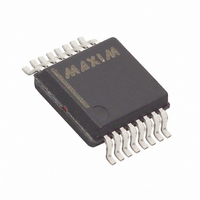
MAX5312EAE+ Maxim Integrated Products, MAX5312EAE+ Datasheet - Page 13

MAX5312EAE+
Manufacturer Part Number
MAX5312EAE+
Description
IC DAC 12BIT 5V/10V SER 16-SSOP
Manufacturer
Maxim Integrated Products
Datasheet
1.MAX5312EAE.pdf
(19 pages)
Specifications of MAX5312EAE+
Settling Time
10µs
Number Of Bits
12
Data Interface
Serial
Number Of Converters
1
Voltage Supply Source
Dual ±
Operating Temperature
-40°C ~ 85°C
Mounting Type
Surface Mount
Package / Case
16-SSOP
Number Of Dac Outputs
1
Resolution
12 bit
Interface Type
Serial (SPI)
Supply Voltage (max)
15.75 V
Supply Voltage (min)
10.8 V
Maximum Operating Temperature
+ 85 C
Mounting Style
SMD/SMT
Maximum Power Dissipation
571 mW
Minimum Operating Temperature
- 40 C
Supply Current
30 uA
Voltage Reference
External
Lead Free Status / RoHS Status
Lead free / RoHS Compliant
Power Dissipation (max)
-
Lead Free Status / Rohs Status
Lead free / RoHS Compliant
The MAX5312 12-bit DAC operates from either single or
dual supplies. Dual ±12V to ±15V power supplies pro-
vide a bipolar ±5V to ±10V output, or a unipolar 0 to 10V
output. Single 12V to 15V power supplies provide only a
unipolar 0 to 10V output. The reference input accepts
voltages from 2V to 5.25V. The DAC features INL and
DNL less than ±1 LSB (max), a fast 10µs settling time,
and a hardware-shutdown mode that reduces current
consumption to 3.5µA (max). The device features a
10MHz SPI-/QSPI-/MICROWIRE-compatible serial inter-
face that operates with 3V or 5V logic, an asynchronous
load input, and a serial-data output. The device offers a
CLR that sets the DAC output to 0V.
functional diagram of the MAX5312.
Figure 1. Functional Diagram
UNI/BIP
DGND
SHDN
LDAC
SCLK
CLR
V
REF
DIN
CS
CC
______________________________________________________________________________________
±10V, 12-Bit, Serial, Voltage-Output DAC
Detailed Description
12
12
12
16-BIT SHIFT REGISTER
SERIAL INTERFACE
INPUT REGISTER
AND CONTROL
DAC REGISTER
12-BIT DAC
Figure 1 shows the
2R
SW1
An SPI-/QSPI-/MICROWIRE-compatible serial interface
allows complete control of the DAC through a 16-bit
control word. The first 4 bits form the control bits that
determine register loading and software-shutdown
functions. The last 12 bits form the DAC data. The 16-
bit word is entered MSB first.
Table 1 shows the serial-data format. Table 2 shows
the interface commands.
The MAX5312 can be programmed while in shutdown.
The serial interface contains three registers: a 16-bit shift
register, a 12-bit input register, and a 12-bit DAC register
(Figure 1). The shift register accepts data from the serial
interface. The input register acts as a holding register for
data going to the DAC register and isolates the shift reg-
ister from the DAC register. The DAC register controls
the DAC ladder and thus the output voltage. Any update
in the DAC register updates the output voltage.
A1
SW3
2R
MAX5312
SW2
A2
Serial Interface
2R
2R
V
OUT
SGND
DOUT
AGND
V
DD
SS
13


