1-2058703-1 TE Connectivity, 1-2058703-1 Datasheet - Page 3
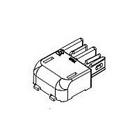
1-2058703-1
Manufacturer Part Number
1-2058703-1
Description
CONNECTOR, BLADE & RECEPTACLE, 2WAY
Manufacturer
TE Connectivity
Datasheet
1.1-2058703-1.pdf
(8 pages)
Specifications of 1-2058703-1
Connector Type
Board To Board
Pitch Spacing
4mm
No. Of Rows
1
No. Of Contacts
2
Gender
Receptacle
Contact Termination
Surface Mount Horizontal
Contact Plating
Tin
Contact Material
Copper
Rohs Compliant
Yes
Colour
Black
Svhc
No SVHC
Product Type
Connector
Sealed
No
Termination Method To Pc Board
Surface Mount
Pcb Mount Retention
With
Pcb Mount Alignment
Without
Smt Compatible
Yes
Mount Angle
Right Angle
Ul File Number
E28476
Keyed
No
Make First / Break Last
No
Mating Retention Type
Latching
Contact Current Rating, Max (a)
5
Operating Voltage (vac)
90
Operating Voltage (vdc)
90
Tail Orientation
In-line
Profile Height (y-axis) (mm [in])
4.13 [0.163]
Centerline (mm [in])
4.00 [0.157]
Number Of Positions
2
Number Of Rows
1
Length (x-axis) (mm [in])
12.25 [0.482]
Width (z-axis) (mm [in])
7.90 [0.311]
Post-mating Assembly Measurement (mm [in])
7.5 [0.295]
Mating Retention
With
Header Mating Direction
Horizontal
Pcb Mount Retention Type
Solder Pads
Tail Plating Material
Matte Tin-Lead over Nickel
Tail Plating, Thickness (µm [?in])
5 [191.85]
Contact Type
Blade/Socket
Contact Plating, Mating Area, Material
Matte Tin
Contact Plating, Mating Area, Thickness (µm [?in])
5 [196.85]
Stamped And Formed
Yes
Connector Style
Hermaphroditic
Mating Alignment
With
Housing Material
Liquid Crystal Polymer (LCP)
Housing Color
Black
Ul Flammability Rating
UL 94V-0
Agency/standard
CSA, UL
Agency/standard Number
C22.2 No. 182.3-M1987, UL 1977
Rohs/elv Compliance
RoHS compliant, ELV compliant
Lead Free Solder Processes
Reflow solder capable to 245°C, Reflow solder capable to 260°C
Rohs/elv Compliance History
Always was RoHS compliant
Circuit Identification Feature
Without
Operating Temperature (°c [°f])
-40 – +105 [-40 – +221]
Applies To
Printed Circuit Board
Lighting Interconnect Level
Level 2
Smt Soldering Temperature (°c [°f])
260 [500]
Glow Wire Rating
No
Uv Exposure Rated
No
Application Use
Board-to-Board
Packaging Method
Tape & Reel
Available stocks
Company
Part Number
Manufacturer
Quantity
Price
Company:

Part Number:
1-2058703-1
Manufacturer:
TE/AMP
Quantity:
30 000


3.3. Contact Crimping
Contacts accept stranded wire only. Strip form contacts are designed to be crimped with a miniature applicator
in a semi--automatic or automatic machine and loose--piece contacts may be crimped using a hand tool. Refer
to the table in Figure 8 for the appropriate hand tools and applicators. Refer to Paragraph 2.5, Instructional
Material, for information on crimping procedures.
3.4. Crimp Requirements
Rev E
NOTE
A. Wire Barrel Crimp
The crimp applied to the wire portion of the contact is the most compressed area and is most critical in
ensuring optimum electrical and mechanical performance of the crimped contact. The contact wire barrel
crimp height must be within the dimension provided in Figure 2.
B. Effective Crimp Length
For optimum crimp effectiveness, the crimp must be within the area shown and must meet the crimp
dimensions provided in Figure 3. Effective crimp length shall be defined as that portion of the wire barrel,
excluding bellmouth(s), fully formed by the crimping tool. Instructions for adjusting, repairing, and
inspecting tools are packaged with the tools. See Section 5, TOOLING.
C. Bellmouths
Front and rear bellmouths shall be as shown and conform to the dimensions given in Figure 3.
D. Cutoff Tabs
The cutoff tab shall be cut to the dimensions shown in Figure 3.
E. Burrs
No burrs allowed.
F. Wire Barrel Flash
The wire barrel flash shall not exceed the dimensions shown in Figure 3, Section X--X.
G. Conductor Extension
The conductor may extend beyond the wire barrel to the maximum shown. No strands may extrude over
the height of the conductor crimp.
H. Wire Barrel Seam
The wire barrel seam shall be closed adequately to confine all strands of the wire. There shall be no loose
strands. Wire strands should not be embedded in the outside of the wire barrel.
I. Locking Lance
The locking lance shall not be deformed.
i
The applied crimp dimension (within the function range of the product) is dependent on the termination tooling being
used. Refer to the documentation (applicator logs and instruction sheets) supplied with the termination tooling for the
applied crimp height. See Section 5, TOOLING.
114- 13252
3 of 8
Related parts for 1-2058703-1
Image
Part Number
Description
Manufacturer
Datasheet
Request
R


Part Number:
Description:
CONNECTOR, SMT-IDC, 2 POS, 20 AWG
Manufacturer:
TE Connectivity
Datasheet:

Part Number:
Description:
CONTACT, RECEPTACLE, 20-16AWG, CRIMP
Manufacturer:
TE Connectivity
Datasheet:
Part Number:
Description:
CONTACT, RECEPTACLE, 20-16AWG, CRIMP
Manufacturer:
TE Connectivity
Datasheet:

Part Number:
Description:
Headers & Wire Housings RECPT 24-20 AWG 30 AU
Manufacturer:
TE Connectivity
Datasheet:

Part Number:
Description:
Manufacturer:
TE Connectivity
Datasheet:

Part Number:
Description:
Manufacturer:
TE Connectivity
Datasheet:

Part Number:
Description:
Manufacturer:
TE Connectivity
Datasheet:

Part Number:
Description:
Manufacturer:
TE Connectivity
Datasheet:

Part Number:
Description:
CONNECTOR, SMT-IDC PASS THRU, 2 POS, 20
Manufacturer:
TE Connectivity
Datasheet:

Part Number:
Description:
Conn D-Subminiature PL 9 POS 2.74mm Solder RA Thru-Hole 9 Terminal 1 Port
Manufacturer:
TE Connectivity
Datasheet:

Part Number:
Description:
Conn D-Subminiature RCP 9 POS 2.74mm Solder RA Thru-Hole 9 Terminal 1 Port
Manufacturer:
TE Connectivity
Datasheet:

Part Number:
Description:
Conn D-Subminiature RCP 9 POS 2.77mm Solder ST Thru-Hole 9 Terminal 1 Port Tray
Manufacturer:
TE Connectivity
Datasheet:

Part Number:
Description:
FFC/FPC CONNECTOR, RECEPTACLE 12POS 1ROW
Manufacturer:
TE Connectivity
Datasheet:

Part Number:
Description:
Manufacturer:
TE Connectivity
Datasheet: