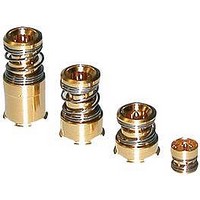
619135-1 TE Connectivity, 619135-1 Datasheet - Page 4

619135-1
Manufacturer Part Number
619135-1
Description
RF/COAXIAL, BNC PLUG, STR, 50OHM, SOLDER
Manufacturer
TE Connectivity
Specifications of 619135-1
Connector Type
BNC Coaxial
Body Style
Straight Plug
Coaxial Termination
Solder
Impedance
50ohm
Contact Material
Phosphor Bronze
Contact Plating
Gold
Frequency Max
6GHz
Rohs Compliant
Yes
Type Of Connector
Compression Coax Board-to-Board
Pcb Mount Style
Surface Mount
Connector Impedance (?)
50
Operating Frequency (mhz)
0 – 6,000
Voltage Rating (vac)
125
Dielectric Withstanding Voltage (v)
500
Insulation Resistance (m?)
100
Length (mm [in])
6.65 [0.262]
Mount Type
Printed Circuit Board
Return Loss (db)
-20
Rohs/elv Compliance
RoHS compliant, ELV compliant
Lead Free Solder Processes
Reflow solder capable to 245°C, Reflow solder capable to 260°C
Rohs/elv Compliance History
Always was RoHS compliant
Operating Temperature (°c [°f])
-40 – +125 [-40 – +257]
Packaging Method
Loose Piece
3.6
Rev E1
Ref.
C1
C2
C3
C4
C5
C6
Initial examination of product.
Final examination of product.
Contact resistance.
VSWR
Insertion loss.
Shielding effectiveness. -60 dB maximum for f ≤ 2’500 MHz
Test Requirements and Procedures Summary
Test Description
With Gold/Silver-plated target board:
With tin-plated target board:
<1.2 up to 2.2 GHz <1.3 up to 3 GHz
<0.2 dB up to 2.2 GHz < 0.25 dB up to 3 GHz
Outer conductor:
≤10 mΩ after 30 Cycle
≤20 mΩ after 5000 Cycle**
≤50 mΩ after 8000 Cycle**
Center conductor:
≤20 mΩ after 30 Cycle
≤50 mΩ after 5000 Cycle**
≤100 mΩ after 8000 Cycle**
Outer conductor:
≤20 mΩ after 30 Cycle
Center conductor:
≤100 mΩ after 30 Cycle
** not valid for PN 1658260
Meets requirements of product and
customer drawings.
Meets visual requirements.
Performance, Requirements
Figure 1 (cont)
ELECTRICAL
VISUAL
IEC 60512-2 test 1a.
Magnification 5x.
Visual, dimensional and functional.
Inspection per product and customer
drawings.
IEC 60512-2 test 1a.
Magnification 5x.
Visual inspection.
IEC 60512-2-2a.
Subject specimens to 30mA
maximum and 20 mV maximum
open circuit voltage.
Measure with target board at
maximum stack height.
See Figure 2.
Measure return loss up to 3’000
MHz at nominal and maximum
misaligned positions, radially and
axially.
See Figure 3.
Measure insertion loss up to 3’000
MHz at nominal and maximum
misaligned positions, radially and
axially.
See Figure 3.
Absorbing Clamp Method in IEC
60096-1 Amendment 2.
Procedure
108-71060
Page 4 of 10


