T0603F104ZCT MULTICOMP, T0603F104ZCT Datasheet - Page 11
T0603F104ZCT
Manufacturer Part Number
T0603F104ZCT
Description
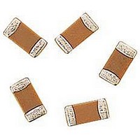
CAPACITOR CERAMIC, 0.1UF, 25V, Y5V, 0603
Manufacturer
MULTICOMP
Datasheet
1.MCCA000432.pdf
(19 pages)
Specifications of T0603F104ZCT
Dielectric Characteristic
Y5V
Capacitance
0.1µF
Capacitance Tolerance
+80, -20%
Voltage Rating
25VDC
Capacitor Case Style
0603
No. Of Pins
2
Capacitor Mounting
SMD
Rohs Compliant
Yes


Precautions for Assembly
Adhesives for Mounting
(1) Selection of adhesives
a. The viscosity of an adhesive for mountings shall be such that the adhesive dose not flow off on the land during its curing.
b. If the adhesive is too low in its viscosity, mounted components may be out of alignment after or during soldering.
c. The adhesives shall not be corrosive or chemically active to the mounted components and the PC boards.
d. The amount of adhesive shall be such that the adhesive does not flow off or be out of alignment.
e. Adhesives for mountings can be cured by ultraviolet or infrared radiation. In order to prevent the terminal electrodes of the
Capacitors the curing shall be done at conditions of 180°C maximum, for 2 minutes maximum.
Chip Mounting consideration
In mounting the Capacitors / components on a printed circuit board, any bending and expanding force against them shall be kept
minimum to prevent them from being damaged or cracked.
Following precautions and recommendation shall be observed carefully in the process:
(1) Maximum stroke of the vacuum nozzle shall be adjusted so that the pushing force to the printed circuit board shall be limited to a
static of 1 to 3 N (100 to 300 gf) (See Figure4).
(2) Maximum stroke of the nozzle shall be adjusted so that the maximum bending of printed circuit board dose not exceeded 0.5mm
(See Figure 4)
Figure 4
(3) The printed circuit board shall be supported by means of adequate supporting pins as shown in Fig.5-(b)
Figure 5
Nickel Barrier
Multilayer Ceramic Capacitors
Page 11
27/04/06 V1.0
Related parts for T0603F104ZCT
Image
Part Number
Description
Manufacturer
Datasheet
Request
R

Part Number:
Description:
INDUCTOR WW 6.8NH 700MA 0603 2%
Manufacturer:
Tamura
Datasheet:
Part Number:
Description:
INDUCTOR WW 100NH 400MA 0603 2%
Manufacturer:
Tamura
Datasheet:

Part Number:
Description:
IC, LINEAR VOLTAGE REGULATOR, 15V, TO-92
Manufacturer:
MULTICOMP
Datasheet:

Part Number:
Description:
Switch Cap
Manufacturer:
MULTICOMP
Datasheet:

Part Number:
Description:
COAXIAL CABLE, 100MM, BLACK
Manufacturer:
MULTICOMP
Datasheet:

Part Number:
Description:
FUSE, PTC RESET, 16V, 3A, RADIAL
Manufacturer:
MULTICOMP
Datasheet:
Part Number:
Description:
FUSE, PTC RESET, 16V, 5A, RADIAL
Manufacturer:
MULTICOMP
Datasheet:

Part Number:
Description:
FUSE, PTC RESET, 30V, 1.85A, RADIAL
Manufacturer:
MULTICOMP
Datasheet:

Part Number:
Description:
FUSE, PTC RESET, 30V, 4A, RADIAL
Manufacturer:
MULTICOMP
Datasheet:

Part Number:
Description:
FUSE, PTC RESET, 60V, 170mA, RADIAL
Manufacturer:
MULTICOMP
Datasheet:

Part Number:
Description:
FUSE, PTC RESET, 90V, 200mA, RADIAL
Manufacturer:
MULTICOMP
Datasheet:
Part Number:
Description:
FUSE, PTC RESET, 90V, 250mA, RADIAL
Manufacturer:
MULTICOMP
Datasheet:
Part Number:
Description:
FUSE, PTC RESET, 90V, 400mA, RADIAL
Manufacturer:
MULTICOMP
Datasheet:
Part Number:
Description:
FUSE, PTC RESET, 90V, 900mA, RADIAL
Manufacturer:
MULTICOMP
Datasheet:

Part Number:
Description:
FUSE, PTC RESET, 90V, 1.6A, RADIAL
Manufacturer:
MULTICOMP
Datasheet: