LTC1450CN Linear Technology, LTC1450CN Datasheet - Page 10
LTC1450CN
Manufacturer Part Number
LTC1450CN
Description
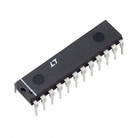
IC D/A CONV 12BIT R-R PAR 24-DIP
Manufacturer
Linear Technology
Datasheet
1.LTC1450CGPBF.pdf
(16 pages)
Specifications of LTC1450CN
Settling Time
14µs
Number Of Bits
12
Data Interface
Parallel
Number Of Converters
1
Voltage Supply Source
Single Supply
Power Dissipation (max)
2mW
Operating Temperature
0°C ~ 70°C
Mounting Type
Through Hole
Package / Case
24-DIP (0.300", 7.62mm)
Lead Free Status / RoHS Status
Contains lead / RoHS non-compliant
Available stocks
Company
Part Number
Manufacturer
Quantity
Price
Company:

Part Number:
LTC1450CN#PBF
Manufacturer:
LT
Quantity:
3 400


OPERATION
Parallel Interface
The data on the input of the DAC is loaded into the DAC’s
input latches when Chip Select (CSLSB and/or CSMSB)
and WR are at a logic low. The data that is loaded into the
input latches will depend on which of the Chip Selects are
at a logic low (see Digital Interface Truth Table). If WR
and CSLSB are both low and CSMSB is high, then only
data on the eight LSBs (D0 to D7) is loaded into the input
latches. Similarly if WR and CSMSB are both low and
CSLSB is high then only data on the four MSBs (D8 to
D11) is loaded into the input latches. Data is loaded into both
the Least Significant Data Bits (D0 to D7) and the Most
Significant Bits (D8 to D11) at the same time if WR, CSLSB
and CSMSB are low.
The input data is latched into the input latches on the rising
edge of either the WR or one of the Chip Selects. The WR
transition high will latch the data in both input latches. A
rising edge on CSMSB will latch data bits D8 to D11. A
rising edge on CSLSB will latch data bits D0 to D7.
Once data is loaded into the input latches, it can be loaded
into the DAC latch. This will update the analog voltage
output of the DAC. The DAC latch is loaded by a logic low
on LDAC. The data that is loaded into the DAC latch will be
latched on the rising edge of LDAC.
When WR, CSLSB, CSMSB and LDAC are all low the
latches are transparent and data on pins D0 to D11 loads
directly into the DAC latch.
Power-On Reset
The LTC1450/LTC1450L have an internal power-on reset
that resets all internal latches to 0’s on power-up (equiva-
lent to the CLR pin function).
Reference
The LTC1450 includes an internal 2.048V reference, giv-
ing the LTC1450 a full-scale range of 4.095V in the gain of
2 configuration. The LTC1450L has an internal 1.22V
reference with a full-scale range of 2.5V and a gain of 2.05
in the gain of 2 configuration. The onboard reference in the
LTC1450 and LTC1450L is not internally connected to the
DAC’s reference resistor string but is provided on an
adjacent pin for flexibility. Because the internal reference
LTC1450/LTC1450L
10
U
is not internally connected to the DAC resistor string, an
external reference can be used or the resistor string can be
driven with an external source in multiplying configura-
tion. The external reference or source must be capable of
driving the 8k minimum DAC ladder resistance.
The reference output noise can be reduced with a bypass
capacitor to ground. (Note: The reference does not require
a bypass capacitor to ground for proper operation.) When
bypassing the reference a small value resistor in series
with the capacitor is recommended to help reduce peaking
on the output. A 10
capacitor is optimum for reducing reference generated
noise.
DAC Ladder Resistor String
The high and low end of the DAC ladder resistor string
(REFHI and REFLO respectively) are not connected inter-
nally on this part. Typically REFHI will be connected to
REFOUT and REFLO will be connected to GND. This will
give the LTC1450 a full-scale range of 4.095V. The full-
scale range for the LTC1450L will be 2.5V
Either of these pins can be driven up to V
using the buffer in the gain of 1 configuration. The resistor
string pins can be driven to V
gain of 2 configuration (2.05 for the LTC1450L). The
resistance between these two pins is typically 18k (8k
min).
Voltage Output
The output buffer for the LTC1450/LTC1450L can be
configured for two different gain settings. By tying the
X1/X2 pin to GND the gain is set to 2 (2.05 for the
LTC1450L). By tying the X1/X2 pin to V
to one.
The LTC1450 family’s rail-to-rail buffered output can source
or sink 5mA over the entire operating temperature range
while pulling to within 300mV of the positive supply
voltage or GND. The output swings to within a few milli-
volts of either supply rail when unloaded and has an
equivalent output resistance of 40 when driving a load to
the rails.
resistor in series with a 4.7 F
CC
/2 when the buffer is in the
OUT
CC
the gain is set
– 1.5V when
Related parts for LTC1450CN
Image
Part Number
Description
Manufacturer
Datasheet
Request
R

Part Number:
Description:
IC D/A CONVERTER 16 BIT 8/MSOP
Manufacturer:
Linear Technology

Part Number:
Description:
CD ROM LINEARVIEW DATASHEETS
Manufacturer:
Linear Technology

Part Number:
Description:
Standalone Linear Li-Ion Battery Charger with Thermal Regulation in ThinSOT
Manufacturer:
Linear Technology Corporation
Datasheet:
Part Number:
Description:
Low noise, high frequency, 8th order linear phase lowpass filter
Manufacturer:
Linear Technology Corporation
Datasheet:
Part Number:
Description:
Manufacturer:
Linear Technology Corporation
Datasheet:
Part Number:
Description:
Manufacturer:
Linear Technology Corporation
Datasheet:
Part Number:
Description:
Manufacturer:
Linear Technology Corporation
Datasheet:
Part Number:
Description:
Manufacturer:
Linear Technology Corporation
Datasheet:
Part Number:
Description:
Manufacturer:
Linear Technology Corporation
Datasheet:
Part Number:
Description:
Manufacturer:
Linear Technology Corporation
Datasheet:
Part Number:
Description:
Manufacturer:
Linear Technology Corporation
Datasheet:
Part Number:
Description:
Dual and Quad, JFET Input Precision High Speed Op Amps
Manufacturer:
Linear Technology Corporation
Datasheet:
Part Number:
Description:
Manufacturer:
Linear Technology Corporation
Datasheet:
Part Number:
Description:
1, 2, 6 and 8 Channel, 10-Bit Serial I/O Data Acquisition Systems
Manufacturer:
Linear Technology Corporation
Datasheet:
Part Number:
Description:
Manufacturer:
Linear Technology Corporation
Datasheet: