AD5621AKSZ-500RL7 Analog Devices Inc, AD5621AKSZ-500RL7 Datasheet - Page 13
AD5621AKSZ-500RL7
Manufacturer Part Number
AD5621AKSZ-500RL7
Description
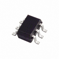
IC DAC 12BIT V-OUT SC70-6
Manufacturer
Analog Devices Inc
Series
nanoDAC™r
Datasheet
1.AD5601BKSZ-REEL7.pdf
(20 pages)
Specifications of AD5621AKSZ-500RL7
Data Interface
SPI™
Settling Time
6µs
Number Of Bits
12
Number Of Converters
1
Voltage Supply Source
Single Supply
Power Dissipation (max)
500µW
Operating Temperature
-40°C ~ 125°C
Mounting Type
Surface Mount
Package / Case
SC-70-6, SC-88, SOT-363
Resolution (bits)
12bit
Sampling Rate
1.7MSPS
Input Channel Type
Serial
Supply Voltage Range - Analog
2.7V To 5.5V
Supply Current
75µA
Digital Ic Case Style
SC-70
Number Of Channels
1
Resolution
12b
Conversion Rate
1.7MSPS
Interface Type
SER 3W SPI QSPI UW
Single Supply Voltage (typ)
3.3/5V
Dual Supply Voltage (typ)
Not RequiredV
Architecture
Resistor-String
Power Supply Requirement
Single
Output Type
Voltage
Integral Nonlinearity Error
±6+/- LSB
Single Supply Voltage (min)
2.7V
Single Supply Voltage (max)
5.5V
Dual Supply Voltage (min)
Not RequiredV
Dual Supply Voltage (max)
Not RequiredV
Operating Temp Range
-40C to 125C
Operating Temperature Classification
Automotive
Mounting
Surface Mount
Pin Count
6
Package Type
SC-70
Package
6SC-70
Digital Interface Type
Serial (3-Wire, SPI, QSPI, Microwire)
Number Of Outputs Per Chip
1
Full Scale Error
±0.5(Typ) mV
Maximum Settling Time
10 us
Lead Free Status / RoHS Status
Lead free / RoHS Compliant
Lead Free Status / RoHS Status
Lead free / RoHS Compliant, Lead free / RoHS Compliant
Other names
AD5621AKSZ500RLTR
Available stocks
Company
Part Number
Manufacturer
Quantity
Price

Part Number:
AD5621AKSZ-500RL7
Manufacturer:
ADI/亚德诺
Quantity:
20 000


TERMINOLOGY
Relative Accuracy
For the DAC, relative accuracy or integral nonlinearity (INL) is
a measure of the maximum deviation, in LSBs, from a straight
line passing through the endpoints of the DAC transfer func-
tion. See Figure 4 to Figure 6 for plots of typical INL vs. code.
Differential Nonlinearity
Differential nonlinearity (DNL) is the difference between the
measured change and the ideal 1 LSB change between any two
adjacent codes. A specified differential nonlinearity of ±1 LSB
maximum ensures monotonicity. This DAC is guaranteed
monotonic by design. See Figure 10 to Figure 12 for plots of
typical DNL vs. code.
Zero-Code Error
Zero-code error is a measure of the output error when zero
code (0x0000) is loaded to the DAC register. Ideally, the output
should be 0 V. The zero-code error is always positive in the
AD5601/AD5611/AD5621 because the output of the DAC cannot
go below 0 V. Zero-code error is due to a combination of the
offset errors in the DAC and output amplifier. Zero-code error
is expressed in mV. See Figure 27 for a plot of zero-code error
vs. temperature.
Full-Scale Error
Full-scale error is a measure of the output error when full-scale
code (0xFFFF) is loaded to the DAC register. Ideally, the output
should be V
Figure 27 for a plot of full-scale error vs. temperature.
Gain Error
Gain error is a measure of the span error of the DAC. It is the
deviation in slope of the DAC transfer characteristic from the
ideal, expressed as a percent of the full-scale range.
DD
− 1 LSB. Full-scale error is expressed in mV. See
Rev. E | Page 13 of 20
Total Unadjusted Error
Total unadjusted error (TUE) is a measure of the output error,
taking all the various errors into account. See Figure 7 to
Figure 9 for plots of typical TUE vs. code.
Zero-Code Error Drift
Zero-code error drift is a measure of the change in zero-code
error with a change in temperature. It is expressed in μV/°C.
Gain Temperature Coefficient
Gain temperature coefficient is a measure of the change in gain
error with changes in temperature. It is expressed in (ppm of
full-scale range)/°C.
Digital-to-Analog Glitch Impulse
Digital-to-analog glitch impulse is the impulse injected into the
analog output when the input code in the DAC register changes
state. It is normally specified as the area of the glitch in nV-s
and is measured when the digital input code is changed by
1 LSB at the major carry transition (0x2000 to 0x1FFF). See
Figure 18.
Digital Feedthrough
Digital feedthrough is a measure of the impulse injected into
the analog output of the DAC from the digital inputs of the
DAC, but is measured when the DAC output is not updated.
It is specified in nV-s and is measured with a full-scale code
change on the data bus—from all 0s to all 1s and vice versa.
AD5601/AD5611/AD5621
Related parts for AD5621AKSZ-500RL7
Image
Part Number
Description
Manufacturer
Datasheet
Request
R

Part Number:
Description:
IC,D/A CONVERTER,SINGLE,12-BIT,CMOS,TSSOP,6PIN
Manufacturer:
Analog Devices Inc
Datasheet:

Part Number:
Description:
±1.7g Dual-Axis IMEMS Accelerometer Evaluation Board
Manufacturer:
Analog Devices Inc
Datasheet:

Part Number:
Description:
Inertial Sensor Evaluation System
Manufacturer:
Analog Devices Inc
Datasheet:
Part Number:
Description:
Manufacturer:
Analog Devices Inc
Datasheet:
Part Number:
Description:
Manufacturer:
Analog Devices Inc
Datasheet:
Part Number:
Description:
Manufacturer:
Analog Devices Inc
Datasheet:
Part Number:
Description:
Manufacturer:
Analog Devices Inc
Datasheet:
Part Number:
Description:
Manufacturer:
Analog Devices Inc
Datasheet:
Part Number:
Description:
Manufacturer:
Analog Devices Inc
Datasheet:
Part Number:
Description:
Manufacturer:
Analog Devices Inc
Datasheet:
Part Number:
Description:
Manufacturer:
Analog Devices Inc
Datasheet:
Part Number:
Description:
Manufacturer:
Analog Devices Inc
Datasheet:
Part Number:
Description:
Manufacturer:
Analog Devices Inc
Datasheet: