KMR213G LFG C&K Components, KMR213G LFG Datasheet
KMR213G LFG
Manufacturer Part Number
KMR213G LFG
Description
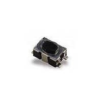
Tactile & Jog Switches Tact
Manufacturer
C&K Components
Type
Micro-Miniaturer
Datasheet
1.KMR231NG_ULC_LFS.pdf
(2 pages)
Specifications of KMR213G LFG
Pole Throw Configuration
SPST
Switch Function Configuration
N.O.
Operating Force
1.2N
Actuator Style
Round Button
Actuator Length (mm)
0.5mm
Current Rating (max)
0.01A
Illumination Type
Not Required
Voltage Rating (vdc)
32V
Ground Terminal
Yes
Contact Material
Gold
Product Length (mm)
2.8mm
Product Depth (mm)
4.6mm
Product Height (mm)
1.9mm
Operating Temp Range
-40C to 125C
Body Orientation
Straight
Mounting Style
Surface Mount
Terminal Type
Gull Wing
Actuator
Oval Standard
Contact Rating
10 mAmps
Contact Form
SPST - NO
Switch Function
Momentary
Termination Style
SMD/SMT
Mounting Direction
Top
Body Size
4.6 mm L x 2.8 mm W x 1.9 mm H
Lead Free Status / Rohs Status
Compliant


Specification
FUNCTION: momentary action
CONTACT ARRANGEMENT: 1 make contact = SPST, N.O.
TERMINALS: Gullwing type for SMT
Mechanical
TACTILE FEELING: for KMR 2 series: ≥ 30% (1.2N at 20%)
Part Number Description
For any part number different from those listed above, please consult your local representative.
KMR211 LFS
KMR213 LFG
KMR221 LFS
KMR223G LFG
KMR231 LFS
KMR233G LFG
KMR231 ULC LFS
KMR232 LFS
KMR232 ULC LFS
KMR241 LFS
KMR243G LFG
KMR241 ULC LFS
KMR242 LFS
KMR242 ULC LFS
Type G and NG
See description
version G only)
(except gold
below
Total height
2
K
1,9 mm
M
Actuation Force
1
2
3
4
1.2 N (120 grams)
2 N (200 grams)
3 N (300 grams)
4 N (400 grams)
R
1.2 (120) ± 0.30
1.2 (120) ± 0.30
2.0 (200) ± 0.50
2.0 (200) ± 0.50
3.0 (300) ± 0.75
3.0 (300) ± 0.75
3.0 (300) ± 0.75
3.0 (300) ± 0.75
3.0 (300) ± 0.75
4.0 (400) ± 1.00
4.0 (400) ± 1.00
4.0 (400) ± 1.00
4.0 (400) ± 1.00
4.0 (400) ± 1.00
Contact Material
1
2
3
Operating
Silver
Silver long life
Gold
N (grs)
force
2
Features/Benefits
•
•
•
•
•
3
Long Life version
4 actuation forces
Optional ground pin
Ultra low current capabilities
Excellent tactile feel
Operating
200 000
200 000
200 000
200 000
150 000
150 000
150 000
300 000
300 000
100 000
100 000
100 000
200 000
200 000
(cycles)
life
1
Grounding option
G
NG
Ground pin
0.20 mm ± 0.1
0.20 mm ± 0.1
0.25 mm ± 0.1
0.25 mm ± 0.1
0.25 mm ± 0.1
0.25 mm ± 0.1
0.25 mm ± 0.1
0.25 mm ± 0.1
0.25 mm ± 0.1
0.30 mm ± 0.1
0.30 mm ± 0.1
0.30 mm ± 0.1
0.30 mm ± 0.1
0.30 mm ± 0.1
No Ground pin
Travel (mm)
N
G
Microminiature SMT Top Actuated
U
B–9
Electrical
MAXIMUM POWER:
MAXIMUM VOLTAGE:
MINIMUM VOLTAGE:
MAXIMUM CURRENT:
MINIMUM CURRENT:
DIELECTRIC STRENGTH:
CONTACT RESISTANCE:
INSULATION RESISTANCE:
BOUNCE TIME:
*For ULC version minimum current is 1µA at 1.8 VDC
Environmental
OPERATING TEMPERATURE:
STORAGE TEMPERATURE:
Process
Infrared Reflow Soldering in accordance with IEC61760-1
Packaging
In reels of 7,000 pieces for KMR 2
External diameter 330 mm ± 2 mm
NOTE: Specifications listed above are for switches with standard options.
For information on specific and custom switches, consult Customer Service Center.
L
C
Low Current capability
Void
ULC
Under standard specification
Low current
L
F
Typical Applications
•
•
•
•
S
Automotive
Cellular phones
Industrial electronics
Medical equipment
LFS
LFG
Lead free compatible, silver plated
Lead free compatible, gold plated
-40˚C to 85˚C
-55˚C to 85˚C
Silver
≥ 250 Vrms
Specifications and dimensions subject to change
≤ 100 mΩ
20 mVDC
32 VDC
≤ 3 ms
50 mA
≥ 1GΩ
1 mA*
Silver
1 VA
KMR 2 Series
www.ck-components.com
Dimensions are shown: Inches (mm)
-40˚C to 125˚C
-55˚C to 125˚C
Gold
20 mVDC
32 VDC
0.2 VA
10 mA
1 mA*
Gold
B
Related parts for KMR213G LFG
Image
Part Number
Description
Manufacturer
Datasheet
Request
R

Part Number:
Description:
Manufacturer:
C&K Components
Datasheet:

Part Number:
Description:
SWITCH TACT SPST-NO 400GF GW SMD
Manufacturer:
C&K Components
Datasheet:

Part Number:
Description:
SWITCH TACT SPST-NO 200GF GW SMD
Manufacturer:
C&K Components
Datasheet:
Part Number:
Description:
SWITCH TACT SPST-NO 120GF GW SMD
Manufacturer:
C&K Components
Datasheet:
Part Number:
Description:
SWITCH TACT SPST-NO 300GF GW SMD
Manufacturer:
C&K Components
Datasheet:
Part Number:
Description:
SWITCH TACT SPST-NO 400GF GW SMD
Manufacturer:
C&K Components
Datasheet:
Part Number:
Description:
SWITCH TACT SPST-NO 300GF GW SMD
Manufacturer:
C&K Components
Datasheet:
Part Number:
Description:
SWITCH TACT SPST-NO 400GF GW SMD
Manufacturer:
C&K Components
Datasheet:
Part Number:
Description:
SWITCH TACT SPST-NO 300GF GW SMD
Manufacturer:
C&K Components
Datasheet:
Part Number:
Description:
SWITCH TACT MICRO MINI SPST SMD
Manufacturer:
C&K Components
Datasheet:

Part Number:
Description:
Rotary Switches 4P 3 POS ROTARY SW
Manufacturer:
C&K Components

Part Number:
Description:
SWITCH MODULE SPST W/CAP L130
Manufacturer:
C&K Components
Datasheet:
Part Number:
Description:
SWITCH MODULE SPST W/CAP
Manufacturer:
C&K Components
Datasheet:

Part Number:
Description:
SWITCH MODULE DPST W/CAP L130
Manufacturer:
C&K Components
Datasheet:
Part Number:
Description:
SWITCH MOD DPST W/CAP L130 PU PO
Manufacturer:
C&K Components
Datasheet:
KMR213G LFG Summary of contents
Page 1
... KMR242 LFS 4.0 (400) ± 1.00 200 000 KMR242 ULC LFS 4.0 (400) ± 1.00 200 000 TACTILE FEELING: for KMR 2 series: ≥ 30% (1.2N at 20%) Part Number Description For any part number different from those listed above, please consult your local representative ...
Page 2
KMR 2 Series Microminiature Tact Switch for SMT KMR 2 Series - 1.9 mm height 4,6 4,2 2,11 2,13 ± 0,1 6 max 0 0,292 ± 0,02 GROUND TERMINAL PCB layout shown with ground pin option 3 ...