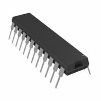
DAC8248FP Analog Devices Inc, DAC8248FP Datasheet - Page 13

DAC8248FP
Manufacturer Part Number
DAC8248FP
Description
IC DAC 12BIT DUAL BUFFERD 24-DIP
Manufacturer
Analog Devices Inc
Datasheet
1.DAC8248FPZ.pdf
(16 pages)
Specifications of DAC8248FP
Rohs Status
RoHS non-compliant
Settling Time
1µs
Number Of Bits
12
Data Interface
Parallel
Number Of Converters
2
Voltage Supply Source
Single Supply
Power Dissipation (max)
50µW
Operating Temperature
-40°C ~ 85°C
Mounting Type
Through Hole
Package / Case
24-DIP (0.300", 7.62mm)
Available stocks
Company
Part Number
Manufacturer
Quantity
Price
Part Number:
DAC8248FP
Manufacturer:
ADI/亚德诺
Quantity:
20 000
loading the appropriate DAC’s digital inputs with 0000 0000
0000 and adjusting the op amp’s offset voltage to 0 V. It is rec-
ommended that the op amp offset voltage be adjusted to less
than 10% of 1 LSB (244 V), and over the operating tempera-
ture range of interest. This will ensure the DAC’s monotonicity
and minimize gain and linearity errors.
BIPOLAR OPERATION
The bipolar (offset binary) 4-quadrant configuration using the
DAC8248 is shown in Figure 8, and the corresponding code is
shown in Table II. The circuit makes use of the OP470, a quad
op amp (use four OP42s for applications requiring higher
speeds).
The full-scale output voltage may be adjusted by varying V
the value of R5 and R8, and thus eliminating resistors R1, R2,
R3, and R4. If resistors R1 through R4 are omitted, then R5, R6,
R7 (R8, R9, and R10 for DAC B) should be ratio-matched to
0.01% to keep gain error within data sheet specifications. The re-
sistors should have identical temperature-coefficients if operating
over the full temperature range.
Zero and full-scale are adjusted in one of two ways and are at
the users discretion. Zero-output is adjusted by loading the ap-
propriate DAC’s digital inputs with 1000 0000 0000 and vary-
ing R1 (R3 for DAC B) so that V
If R1, R2 (R3, R4 for DAC B) are omitted, then zero output
can be adjusted by varying R6, R7 ratios (R9, R10 for DAC B).
Full-scale is adjusted by loading the appropriate DAC’s digital
inputs with 1111 1111 1111 and varying R5 (R8 for DAC B).
REV. B
OUT A
Figure 8. Bipolar Configuration (4-Quadrant Multiplication)
(or V
OUT B
) equals 0 V.
REF
or
–13–
SINGLE SUPPLY OPERATION
CURRENT STEERING MODE
Because the DAC8248’s R-2R resistor ladder terminating resis-
tor is internally connected to AGND, it lends itself well for
single supply operation in the current steering mode configura-
tion. This means that AGND can be raised above system
Binary Number in
DAC Register
MSB
1111 1111 1111
1000 0000 0001
1000 0000 0000
0111 1111 1111
0000 0000 0000
NOTE:
1 LSB=(2
Table II. Bipolar (Offset Binary) Code Table
(Refer to Figure 8)
–11
)(V
REF
LSB
) =
2048
1
(V
REF
)
Analog Output, V
(DAC A or DAC B)
+V
+V
0 V
–V
–V
REF
REF
REF
REF
2048
2048
2048
2047
2048
2048
1
1
DAC8248
OUT


