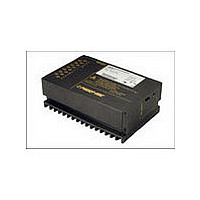
PSK1212-9 POWER ONE, PSK1212-9 Datasheet - Page 16

PSK1212-9
Manufacturer Part Number
PSK1212-9
Description
Manufacturer
POWER ONE
Type
Step Downr
Datasheet
1.PSK1212-9.pdf
(20 pages)
Specifications of PSK1212-9
Output Current
12A
Input Voltage
18 to 144V
Output Voltage
12V
Number Of Outputs
1
Output Power
144
Screening Level
Commercial
Operating Temperature Min Deg. C
-40C
Operating Temperature Max Deg. C
71C
Product Length (mm)
168.5mm
Product Depth (mm)
111mm
Product Height (mm)
80mm
Mounting Style
Screw
Pin Count
15
Lead Free Status / Rohs Status
Not Compliant
Fig. 12
View of H15 and H15S4 male connector
Safety and Installation Instructions
Connector Pin Allocation
The connector pin allocation table defines the electrical
potentials and the physical pin positions on the H15 or H15S4
connector. Pin 24 (protective earth) is a leading pin, which
provides electrical contact first. The regulators should only be
wired via the female connector H15 (according to DIN 41612)
to ensure requested safety!
Table 12: H15 and H15S4 connector pin allocation
BCD20029-G Rev AA, 28-Apr-09
Electrical Determination
Output voltage (positive)
Output voltage (positive)
Output voltage (negative)
Output voltage (negative)
Crowbar trigger input (option C)
Inhibit input
R-input (output voltage programming)
Sense line (negative)
Sense line (positive)
Current sharing control input
Protective ground (leading pin)
Input voltage (negative)
Input voltage (negative)
Input voltage (positive)
Input voltage (positive)
1
Not available with option P
30/32
32
Fixtures for connector
Fixtures for connector
®
(see Accessories)
(see Accessories)
retention clips V
retention clips V
Type H15S4
Type H15
1
Pin no.
18
20
10
12
14
16
22
24
26
28
30
32
4
6
8
Type H15
10010a
4/6
4
Ident.
Vo+
Vo+
Go–
Go–
Gi–
Gi–
Vi+
Vi+
R
S–
S+
C
T
i
1
Pin no. Ident.
26/28
30/32
Type H15S4
8/10
4/6
12
14
16
18
20
22
24
Page 16 of 20
Go–
Vo+
Gi–
Vi+
R
S–
S+
C
T
i
Installation Instruction
Installation of the regulators must strictly follow the national
safety regulations in compliance with the enclosure, mounting,
creepage, clearance, casualty, markings, and segregation
requirements of the end-use application.
The input and the output circuit are not separated. The
negative path is internally interconnected.
The regulators should be connected to a secondary circuit.
Make sure that a regulator failure (e.g. by an internal short-
circuit) does not result in a hazardous condition.
Do not open the regulator!
Standards and Approvals
All switching regulators are class-I equipments and have been
approved according to UL 60950, CSA 60950, and IEC/EN
60950.
The regulators have been evaluated for:
The switching regulators are subject to manufacturing
surveillance in accordance with the above mentioned
standards and with ISO 9001:2000.
Cleaning Agents
In order to avoid possible damage, any penetration of cleaning
fluids must be prevented, since the regulators are not
hermetically sealed.
1
• Connecting the input to a secondary circuit, which is subject
• Building in
• Operational insulation from input to output and input/output
• The use in a pollution degree 2 environment
to case
to a maximum transient rating of 1500 V.
Protection Degree
The protection degree is IP 30 (IP 20, if equipped with
option P). It applies only, if the regulator is plugged-in or
the matching female connector is properly attached.
Isolation and Protective Earth
The resistance of the protective earth connection (max.
0.1
input interconnected with the output and the case is
tested with 500 VDC (all -2 models), 750 VDC (models
with V
144), 1 s.
These tests are performed in the factory as routine test
in accordance with EN 50116 and IEC/EN 60950. The
electric strength test should not be repeated by the
customer. Power-One will not honor any warranty
claims resulting from electric strength tests.
Railway Application
The regulators have been developed observing the
railway standards EN 50155 and EN 50121. All boards
are coated with a protective lacquer.
) is tested. Also the electric strength between the
i max
Positive Switching Regulators
= 80 V), or 1500 VDC (models with V
PSS, PSK Series Data Sheet
www.power-one.com
i max
=


