AD664AD-UNI Analog Devices Inc, AD664AD-UNI Datasheet - Page 6
AD664AD-UNI
Manufacturer Part Number
AD664AD-UNI
Description
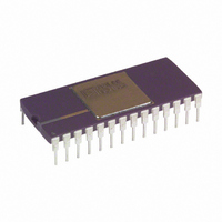
IC DAC 12BIT QUAD UNIPOL 28-CDIP
Manufacturer
Analog Devices Inc
Datasheet
1.AD664JNZ-BIP.pdf
(20 pages)
Specifications of AD664AD-UNI
Rohs Status
RoHS non-compliant
Settling Time
8µs
Number Of Bits
12
Data Interface
Parallel
Number Of Converters
4
Voltage Supply Source
Dual ±
Power Dissipation (max)
525mW
Operating Temperature
-40°C ~ 85°C
Mounting Type
Through Hole
Package / Case
28-CDIP (0.600", 15.24mm)
Available stocks
Company
Part Number
Manufacturer
Quantity
Price


AD664
ANALOG CIRCUIT CONSIDERATIONS
Grounding Recommendations
The AD664 has two pins, designated ANALOG and DIGITAL
ground. The analog ground pin is the “high quality” ground ref-
erence point for the device. A unique internal design has
resulted in low analog ground current. This greatly simplifies
management of ground current and the associated induced volt-
age drops. The analog ground pin should be connected to the
analog ground point in the system. The external reference and
any external loads should also be returned to analog ground.
The digital ground pin should be connected to the digital
ground point in the circuit. This pin returns current from the
logic portions of the AD664 circuitry to ground.
Analog and digital grounds should be connected at one point in
the system. If there is a possibility that this connection be bro-
ken or otherwise disconnected, then two diodes should be con-
nected between the analog and digital ground pins of the
AD664 to limit the maximum ground voltage difference.
Power Supplies and Decoupling
The AD664 requires three power supplies for proper operation.
V
+5 volts. V
cuitry and require +12 V to +15 V and –12 V to –15 V, respec-
tively. V
then the maximum reference and output voltages anticipated.
Decoupling capacitors should be used on all power supply pins.
Good engineering practice dictates that the bypass capacitors be
located as near as possible to the package pins. V
bypassed to digital ground. V
analog ground.
Driving the Reference Input
The reference input of the AD664 can have an impedance as
low as 1.3 k . Therefore, the external reference voltage must be
able to source up to 7.7 mA of load current. Suitable choices
include the 5 V AD586, the 10 V AD587 and the 8.192 V
AD689.
The architecture of the AD664 derives an inverted version of
the reference voltage for some portions of the internal circuitry.
This means that the power supplies must be at least 2 V
LL
powers the logic portions of the device and requires
CC
Figure 2. Recommended Circuit Schematic
CC
and V
and V
EE
EE
must also be a minimum of two volts greater
power the remaining portions of the cir-
CC
and V
EE
should be decoupled to
LL
should be
–6–
greater than both the external reference and the inverted exter-
nal reference.
Output Considerations
Each DAC output can source or sink 5 mA of current to an
external load. Short-circuit protection limits load current to a
maximum load current of 40 mA. Load capacitance of up to
500 pF can be accommodated with no effect on stability.
Should an application require additional output current, a cur-
rent boosting element can be inserted into the output loop with
no sacrifice in accuracy. Figure 3 details this method.
AD664 output voltage settling time is 10 s maximum. Figure 4
shows the output voltage settling time with a fixed 10 V refer-
ence, gain = 1 and all bits switched from 1 to 0.
Alternately, Figure 5 shows the settling characteristics when the
reference is switched and the input bits remain fixed. In this
case, all bits are “on,” the gain is 1 and the reference is switched
from –5 V to +5 V.
Figure 4. Settling Time; All Bits Switched from On to Off
Figure 5. Settling Time; Input Bits Fixed, Reference
Switched
Figure 3. Current-Boosting Scheme
REV. C
Related parts for AD664AD-UNI
Image
Part Number
Description
Manufacturer
Datasheet
Request
R

Part Number:
Description:
IC,D/A CONVERTER,QUAD,12-BIT,BICMOS,DIP,28PIN
Manufacturer:
Analog Devices Inc
Datasheet:

Part Number:
Description:
±1.7g Dual-Axis IMEMS Accelerometer Evaluation Board
Manufacturer:
Analog Devices Inc
Datasheet:

Part Number:
Description:
Inertial Sensor Evaluation System
Manufacturer:
Analog Devices Inc
Datasheet:
Part Number:
Description:
Manufacturer:
Analog Devices Inc
Datasheet:
Part Number:
Description:
Manufacturer:
Analog Devices Inc
Datasheet:
Part Number:
Description:
Manufacturer:
Analog Devices Inc
Datasheet:
Part Number:
Description:
Manufacturer:
Analog Devices Inc
Datasheet:
Part Number:
Description:
Manufacturer:
Analog Devices Inc
Datasheet:
Part Number:
Description:
Manufacturer:
Analog Devices Inc
Datasheet:
Part Number:
Description:
Manufacturer:
Analog Devices Inc
Datasheet:
Part Number:
Description:
Manufacturer:
Analog Devices Inc
Datasheet:
Part Number:
Description:
Manufacturer:
Analog Devices Inc
Datasheet:
Part Number:
Description:
Manufacturer:
Analog Devices Inc
Datasheet: