KB16SKW01-12-CC-RO NKK Switches, KB16SKW01-12-CC-RO Datasheet - Page 5
KB16SKW01-12-CC-RO
Manufacturer Part Number
KB16SKW01-12-CC-RO
Description
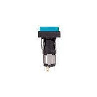
Pushbutton Switches SPDT ON-ON
Manufacturer
NKK Switches
Type
Alternate Contactr
Series
KBr
Datasheet
1.AT701.pdf
(13 pages)
Specifications of KB16SKW01-12-CC-RO
Pole Throw Configuration
SPDT
Switch Configuration
ON ON
Actuator Style
Square Button
Current Rating (max)
1A
Illumination Type
Incandescent Lamp
Ac Voltage Rating (max)
250VVAC
Dc Voltage Rating (max)
30VVDC
Contact Material
Silver
Housing Material
Polyamide/Polyamide
Product Height (mm)
38.5mm
Product Depth (mm)
14mm
Product Length (mm)
14mm
Operating Temp Range
-25C to 50C
Mounting Style
Panel
Terminal Type
Solder Lug
Contact Form
SPDT
Switch Function
ON - ON
Contact Rating
1 Amp at 125 VoltsAC, 250 VoltsAC
Termination Style
Solder Lug
Actuator
Square
Cap Color
Red, Red
Supply Voltage
125 VoltsAC, 250 VoltsAC
Terminal Seal
Molded
Contact Plating
Silver
Illumination
Illuminated
Flammability Rating
UL 94 V-0
Body Length
24.7 mm
Body Shape
Square
Dielectric Strength
1500 Volts AC
Features
Snap-action mechanism for long life; front panel relamping; latchdown feature gives indication of circuit status; incandescent lamp
Insulation Resistance
1000 MOhms
Led Size
T-1 Bi-pin
Led Supply Voltage
12 VoltsAC
Mounting Angle
Straight
Operating Force
2.45 N
Lead Free Status / Rohs Status
Compliant


Miniature Pushbuttons
A partitioned plastic guard is supplied with each switch to provide insulation between terminals.
Installation steps:
AT611
Incandescent
AT634
5-volt
2-element
with 1 Resistor
AT634
LEDs are colored
in OFF state.
No Code
No Code
W
G
1. Identify wire-to-terminal connections.
2. Thread wires through the guard.
Silver Contacts
Gold Contacts
Complete explanation of operating range in Supplement section.
LED circuit is isolated and requires external power source. Polarity marks are on the bottom of the switch.
T-1
T-1 Bi-pin
(+)
1
⁄
4
No Barrier
Built-in bezel
No Lamp
Bi-pin
The resistor value can be calculated by using the formula in the Supplement section.
The electrical specifications shown are determined at a basic temperature of 25°C.
AT615
Neon
If the source voltage exceeds the rated voltage, a ballast resistor is required.
Power Level
1A @ 125V AC & 250V AC
CONTACT MATERIALS, RATINGS & TERMINALS
Logic Level
0.4VA maximum @ 28V AC/DC
Ambient Temperature Range for lamps below: –25°C ~ +50°C.
(-)
Color Codes:
Forward Peak Current
Continuous Forward Current
Forward Voltage
Reverse Peak Voltage
Current Reduction Rate Above 25°C
Voltage
Current
Endurance
LAMP COLORS & SPECIFICATIONS
AT634
12-volt
4-element
with 2 Resistors
Incandescent & Neon Lamps
3. Solder the connections.
4. Push the guard fully onto the switch body.
AT055 Crossover Guard
Bright LED with Resistor
(+)
BARRIER TYPE
Red
5C
V
I
Hours
www.nkk.com
B
115mA
Amber
5V AC
5D
05
7,000 average
With Barrier
Built-in barrier only available for Square and Rectangular
Green
12V AC
01
60mA
5F
(-)
12
I
I
V
V
∆I
FM
F
F
RM
F
AT634
24-volt
4-element
with 2 Resistors
Solder Lug
110V AC
10,000
25mA
1.5mA
05
5V
4V
—
—
01
(+)
Resistor Codes
.079
Thk = (0.2)
(2.0)
Series KB
.039
(1.0)
Recommended Resistors
for Neon:
33K ohms for 110V AC;
100K ohms for 220V AC
(12.4) Dia
.488
20mA
.008
12V
12
8V
—
—
Com = (0.1)
.071
(1.8)
(5.0)
.197
.005
(14.0) Dia
.551
(17.0)
.669
10mA
24V
16V
24
—
—
D27
(-)
D
Related parts for KB16SKW01-12-CC-RO
Image
Part Number
Description
Manufacturer
Datasheet
Request
R

Part Number:
Description:
Pushbutton Switches SPDT ON-ON SQ RED
Manufacturer:
NKK Switches
Datasheet:
Part Number:
Description:
Pushbutton Switches SPDT ON-ON SQR AMB
Manufacturer:
NKK Switches
Datasheet:
Part Number:
Description:
Pushbutton Switches SPDT ON-ON SQR RED
Manufacturer:
NKK Switches
Part Number:
Description:
Pushbutton Switches SPDT ON-ON SQR WHT
Manufacturer:
NKK Switches
Part Number:
Description:
SW PB SPDT ALT SQ SILVER SLD MT
Manufacturer:
NKK Switches
Datasheet:

Part Number:
Description:
SWITCH PB ILLUM SPDT 1A GRN
Manufacturer:
NKK Switches
Datasheet:
Part Number:
Description:
SW PB ILLUM SPDT ALT SQ RED SLD
Manufacturer:
NKK Switches
Datasheet:
Part Number:
Description:
SW PB ILLUM SPDT ALT SQ WHT SLD
Manufacturer:
NKK Switches
Datasheet:
Part Number:
Description:
SW PB ILLUM SPDT ALT SQ GRN SLD
Manufacturer:
NKK Switches
Datasheet:
Part Number:
Description:
SWITCH ILLUM PB SPDT SLD 5V CLR
Manufacturer:
NKK Switches
Datasheet:
Part Number:
Description:
SW ILLUM PB SPDT SQ 12V WHITE
Manufacturer:
NKK Switches
Datasheet:
Part Number:
Description:
SW PB ILLUM SPDT ALT SQ RED SLD
Manufacturer:
NKK Switches
Datasheet:
Part Number:
Description:
SW PB ILLUM SPDT ALT SQ RED SLD
Manufacturer:
NKK Switches
Datasheet:
Part Number:
Description:
SW PB ILLUM SPDT ALT SQ RED SLD
Manufacturer:
NKK Switches
Datasheet:
Part Number:
Description:
SW PB ILLUM SPDT ALT SQ GRN SLD
Manufacturer:
NKK Switches
Datasheet: