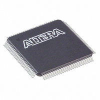
EPM3064ATC100-4 Altera, EPM3064ATC100-4 Datasheet - Page 39

EPM3064ATC100-4
Manufacturer Part Number
EPM3064ATC100-4
Description
IC MAX 3000A CPLD 64 100-TQFP
Manufacturer
Altera
Series
MAX® 3000Ar
Datasheet
1.EPM3032ATC44-10N.pdf
(46 pages)
Specifications of EPM3064ATC100-4
Programmable Type
In System Programmable
Delay Time Tpd(1) Max
4.5ns
Voltage Supply - Internal
3 V ~ 3.6 V
Number Of Logic Elements/blocks
4
Number Of Macrocells
64
Number Of Gates
1250
Number Of I /o
66
Operating Temperature
0°C ~ 70°C
Mounting Type
Surface Mount
Package / Case
100-TQFP, 100-VQFP
Voltage
3.0 V ~ 3.6 V
Memory Type
EEPROM
Number Of Logic Elements/cells
4
Family Name
MAX 3000A
# Macrocells
64
Number Of Usable Gates
1250
Frequency (max)
250MHz
Propagation Delay Time
4.5ns
Number Of Logic Blocks/elements
4
# I/os (max)
66
Operating Supply Voltage (typ)
3.3V
In System Programmable
Yes
Operating Supply Voltage (min)
3V
Operating Supply Voltage (max)
3.6V
Operating Temp Range
0C to 70C
Operating Temperature Classification
Commercial
Mounting
Surface Mount
Pin Count
100
Package Type
TQFP
Lead Free Status / RoHS Status
Contains lead / RoHS non-compliant
Features
-
Lead Free Status / Rohs Status
Not Compliant
Other names
544-1157
Available stocks
Company
Part Number
Manufacturer
Quantity
Price
Company:
Part Number:
EPM3064ATC100-4
Manufacturer:
ALTERA
Quantity:
3
Part Number:
EPM3064ATC100-4
Manufacturer:
ALTERA/阿尔特拉
Quantity:
20 000
Company:
Part Number:
EPM3064ATC100-4N
Manufacturer:
ALTERA
Quantity:
1 600
Power
Consumption
Altera Corporation
Supply power (P) versus frequency (f
devices is calculated with the following equation:
P = P
The P
and switching frequency, can be calculated using the guidelines given in
Application Note 74 (Evaluating Power for Altera
The I
logic. The I
I
(A × MC
The parameters in the I
MC
MC
MC
f
tog
A, B, C
The I
conditions using a pattern of a 16–bit, loadable, enabled, up/down
counter in each LAB with no output load. Actual I
during operation because this measurement is sensitive to the actual
pattern in the device and the environmental operating conditions.
Figures 12
MAX 3000A devices.
CCINT
MAX
Table 26. MAX 3000A I
LC
TON
DEV
USED
CCINT
CCINT
INT
IO
EPM3032A
EPM3064A
EPM3128A
EPM3256A
EPM3512A
=
value, which depends on the device output load characteristics
TON
+ P
Device
= Number of macrocells with the Turbo Bit
= Number of macrocells in the device
= Total number of macrocells in the design, as reported in
= Highest clock frequency to the device
= Average percentage of logic cells toggling at each clock
= Constants (shown in
and
CCINT
value depends on the switching frequency and the application
calculation provides an I
IO
) + [B × (MC
on, as reported in the Quartus II or MAX+PLUS II Report
File (.rpt)
the RPT File
(typically 12.5%)
= I
13
MAX 3000A Programmable Logic Device Family Data Sheet
value is calculated with the following equation:
CCINT
show the typical supply current versus frequency for
CC
CCINT
× V
Equation Constants
DEV
CC
– MC
equation are:
+ P
0.71
0.71
0.71
0.71
0.71
A
IO
TON
Table
CC
MAX
)] + (C × MC
estimate based on typical
26)
, in MHz) for MAX 3000A
Devices).
0.30
0.30
0.30
0.30
0.30
B
CC
USED
should be verified
TM
× f
option turned
MAX
0.014
0.014
0.014
0.014
0.014
× tog
C
LC
39
)


