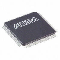
EPM240GT100C3 Altera, EPM240GT100C3 Datasheet - Page 32

EPM240GT100C3
Manufacturer Part Number
EPM240GT100C3
Description
IC MAX II CPLD 240 LE 100-TQFP
Manufacturer
Altera
Series
MAX® IIr
Specifications of EPM240GT100C3
Programmable Type
In System Programmable
Delay Time Tpd(1) Max
4.7ns
Voltage Supply - Internal
1.71 V ~ 1.89 V
Number Of Logic Elements/blocks
240
Number Of Macrocells
192
Number Of I /o
80
Operating Temperature
0°C ~ 85°C
Mounting Type
Surface Mount
Package / Case
100-TQFP, 100-VQFP
Voltage
1.8V
Memory Type
FLASH
Number Of Logic Elements/cells
240
Lead Free Status / RoHS Status
Contains lead / RoHS non-compliant
Features
-
Other names
544-1147
EPM240TG100C3
RPM240GT100C3
EPM240TG100C3
RPM240GT100C3
Available stocks
Company
Part Number
Manufacturer
Quantity
Price
2–24
Figure 2–19. MAX II IOE Structure
Note to
(1) Available in EPM1270 and EPM2210 devices only.
I/O Blocks
MAX II Device Handbook
Figure
Data_in
2–19:
Fast_out
The IOEs are located in I/O blocks around the periphery of the MAX II device. There
are up to seven IOEs per row I/O block (5 maximum in the EPM240 device) and up to
four IOEs per column I/O block. Each column or row I/O block interfaces with its
adjacent LAB and MultiTrack interconnect to distribute signals throughout the device.
The row I/O blocks drive row, column, or DirectLink interconnects. The column I/O
blocks drive column interconnects.
Data_out
OE
Drive Strength Control
Programmable
Input Delay
Open-Drain Output
DEV_OE
Slew Control
Optional Schmitt
Trigger Input
Optional
PCI Clamp (1)
V
CCIO
V
CCIO
I/O Pin
Programmable
Pull-Up
© October 2008 Altera Corporation
Optional Bus-Hold
Circuit
Chapter 2: MAX II Architecture
I/O Structure


