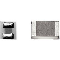
CH02016-150RGFT Vishay, CH02016-150RGFT Datasheet - Page 4

CH02016-150RGFT
Manufacturer Part Number
CH02016-150RGFT
Description
High Frequency/RF Resistors 30mWatt 150ohms 2%
Manufacturer
Vishay
Series
CHr
Datasheet
1.CH0402-50UJNT.pdf
(10 pages)
Specifications of CH02016-150RGFT
Resistance
150 Ohms
Tolerance
2 %
Power Rating
30 mWatts
Package / Case
02016
Temperature Coefficient
+/- 100 PPM / C
Frequency
50 GHz
Voltage Rating
30 Volts
Operating Temperature Range
- 55 C to + 155 C
Termination Style
SMD/SMT
Dimensions
0.39 mm W x 0.5 mm L x 0.42 mm H
Lead Free Status / Rohs Status
Lead free / RoHS Compliant
TYPICAL HIGH FREQUENCY PERFORMANCE ELECTRICAL MODEL
The complex impedance of the chip resistor is given by the following equations:
Notes:
• ω = 2 x π x f
• f: Frequency
The chip resistor itself is purely resistive when
which the resistor looks approximately resistive.
This can be seen on the graphs showing the ratio
R, L and C are relevant to the chip resistor itself.
L
It is important to notice that after assembly the external reactance of L
C. This combination can upgrade or downgrade the HF behaviour of the component.
This is why we are displaying two sets of data:
•
• S-parameters versus frequency curves relevant to chip resistor when assembled on ideal Z
These lines are terminated with adapted source and load impedance respectively Z
configurations please consult us).
Equivalent circuit for S-parameters:
S-parameters are computed taking into account all the resistive, inductive and capacitive elements (Z total) and Z
Document Number: 53014
Revision: 29-Nov-10
c
C
L
R
Z
L
C
Z [ ]
------- -
and C
c
R
g
versus
g
also depends on the way the chip resistor is mounted.
frequency curves which aims to show at a glance the intrinsic HF performance of a given chip resistor
G
Z
S
Z
0
Z [ ]
------- -
Z total
Z
R
0
=
50 GHz Thin Film Microwave Resistors
------------------------------------------------------------------------------------------ - x
1
+
C
C R
g
[
For technical questions, contact:
(
2
L
C
c
L
Z
c
–
R
θ
=
Z [ ]
------- -
Z
2L
1
=
=
-------------------------------------------------------------------------------------- -
1
R
R
+
tan
)ω
C R
versus frequency.
--- -
C
L
+
2
–
[
L
. The smaller the L x C product the greater the frequency range over
1
(
+
L
jω L
ω L
------------------------------------------------------------ -
2
(
L
(
C
2
Cω
–
–
–
C
R
R
2L
C
4
2
]
2
C
C
)ω
R
External connection inductance
External capacitance to ground
Internal impedance (R, L, C)
–
2
R
–
Internal shunt capacitance
R
1
c
sfer@vishay.com
+
L
L
+
and C
2
Internal inductance
2
L
Cω
Cω
2
ω L
------------------------------------------------------------ -
Cω
Resistance
(
2
2
)
)
g
4
–
L
]
c
will be combined to internal reactance of L and
L
R
c
2
C
R
C
–
C
g
s
g
L
2
and Z
Cω
0
2
)
impedance transmission line
l
2
Z
with Z
0
Z
0
Vishay Sfernice
0
= Z
Z
L
L
= Z
0
www.vishay.com
= Z
s
(for others
L
= Z
CH
s
= R.
49


