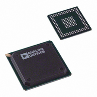
ADSP-BF531SBBZ400 Analog Devices Inc, ADSP-BF531SBBZ400 Datasheet - Page 11

ADSP-BF531SBBZ400
Manufacturer Part Number
ADSP-BF531SBBZ400
Description
IC DSP CTLR 16BIT 400MHZ 169BGA
Manufacturer
Analog Devices Inc
Series
Blackfin®r
Type
Fixed Pointr
Datasheet
1.ADSP-BF531SBSTZ400.pdf
(12 pages)
Specifications of ADSP-BF531SBBZ400
Interface
SPI, SSP, UART
Clock Rate
400MHz
Non-volatile Memory
ROM (1 kB)
On-chip Ram
52kB
Voltage - I/o
1.8V, 2.5V, 3.3V
Voltage - Core
1.20V
Operating Temperature
-40°C ~ 85°C
Mounting Type
Surface Mount
Package / Case
169-BGA
No. Of Bits
16 Bit
Frequency
400MHz
Supply Voltage
1.2V
Embedded Interface Type
PPI, SPI, UART
No. Of I/o's
16
Supply Voltage Range
0.8V To 1.45V, 1.75V To 3.6V
Device Core Size
16b
Architecture
Modified Harvard
Format
Fixed Point
Clock Freq (max)
400MHz
Mips
400
Device Input Clock Speed
400MHz
Operating Supply Voltage (typ)
1.2/1.8/2.5/3.3V
Operating Supply Voltage (min)
0.8/1.75V
Operating Supply Voltage (max)
1.32/3.6V
Operating Temp Range
-40C to 85C
Operating Temperature Classification
Industrial
Mounting
Surface Mount
Pin Count
169
Package Type
BGA
Lead Free Status / RoHS Status
Lead free / RoHS Compliant
For Use With
ADZS-BF533-EZLITE - KIT W/BOARD EVAL FOR ADSP-BF533
Lead Free Status / Rohs Status
Compliant
Available stocks
Company
Part Number
Manufacturer
Quantity
Price
Company:
Part Number:
ADSP-BF531SBBZ400
Manufacturer:
HYDAI
Quantity:
50
Company:
Part Number:
ADSP-BF531SBBZ400
Manufacturer:
Analog Devices Inc
Quantity:
10 000
Part Number:
ADSP-BF531SBBZ400
Manufacturer:
ADI/亚德诺
Quantity:
20 000
Companion Power Selection Guide for the Blackfin Processor
ADI power management products provide optimized power for Blackfin products — w hether
it’s a single processor or multiple processors, in handheld or high power applications, ADI
has a solution to meet your needs.
How to Use This Guide
Determine the peak current requirement for each rail of your processor by referring to the
relevant data sheets and engineer-to-engineer notes. Then, use this companion guide to
select a power solution that offers the required V
The ADIsimPower
BOM for all of these solutions. Visit www.analog.com/ADIsimPower.
• Indicates that the regulator will support the current draw at the maximum specified frequency, voltage, and industrial temperature.
•
*Refer to the relevant data sheet and engineer-to-engineer note to determine the exact “other domain” requirements of each individual processor.
Many applications power more than one device or domain using a single regulator. Compute and add the maximum current draw for each device and domain in a particular application before choosing a regulator.
Indicates that the regulator will support the current draw in some applications, but the maximum IDD
ADSP-BF522/ADSP-BF524/ADSP-BF526
ADSP-BF523/ADSP-BF525/ADSP-BF527
ADSP-BF531/ADSP-BF532/ADSP-BF533
ADSP-BF534/ADSP-BF536/ADSP-BF537
Blackfin Processors
ADSP-BF534/ADSP-BF536
ADSP-BF538/ADSP-BF539
ADSP-BF50x
ADSP-BF51x
ADSP-BF533
ADSP-BF54x
ADSP-BF54x
ADSP-BF561
™
VDD
VDD
VDD
VDD
VDD
design tool offers a complete set of features to create a complete
MEM
DDR
USB
OTP
EXT
Min Voltage ( V )
500, 533, 600
500, 533, 600
Speed ( MHz )
300, 400
400, 533
533, 600
2.25
400
400
1.7
1.7
2.5
All
All
All
All
All
3
OUT
for that rail.
Nominal Voltages ( V )
Min Voltage ( V )
1.8, 2.5, 3.3
1.8, 2.5, 3.3
1.235
0.95
1.1
1.1
0.8
0.8
0.8
0.8
0.8
0.9
0.9
0.8
2.6
3.3
2.5
INT
must be calculated using the appropriate Blackfin data sheet to ensure compatibility.
Max Voltage ( V )
Max Voltage ( V )
1.375
1.47
1.47
1.47
1.26
1.32
1.45
1.32
1.43
1.43
1.43
1.42
2.75
3.6
3.6
2.7
3.6
Max Current ( mA )
Max IDD
1350
1600
300
250
250
500
350
900
400
900
850
750
N/A
N/A
N/A
30
25
INT
( mA )
•
•
•
•
•
•
•
•
•
•
•
•
•
•
•
•
•
•
•
•
•
•
•
•
LDO Regulators
•
•
•
•
•
•
•
•
•
•
•
•
•
•
•
•
•
•
•
•
•
•
•
•
•
•
•
•
•
•
•
•
•
•
•
•
•
•
•
•
•
•
•
•
•
•
•
•
•
•
•
•
•
•
•
•
•
•
•
•
•
•
•
•
•
•
•
•
•
•
•
•
•
•
•
•
•
•
•
•
•
•
•
•
•
•
•
•
•
•
•
•
•
•
•
•
•
•
•
•
•
•
•
•
•
•
•
•
•
•
•
•
•
•
•
•
•
•
•
•
•
•
•
•
•
•
•
•
•
•
•
•
•
•
•
•
•
•
•
•
•
•
•
•
•
•
•
•
•
•
Switching Regulators and Controllers
•
•
•
•
•
•
•
•
•
•
•
•
•
•
•
•
•
•
•
•
•
•
•
•
•
•
•
•
•
•
•
•
•
•
•
•
•
•
•
•
•
•
•
•
•
•
•
•
•
•
•
•
•
•
•
•
•
•
•
•
•
•
•
•
•
•
•
•
•
•
•
•
•
•
•
•
•
•
•
•
•
•
•
•
•
•
•
•
•
•
•
•
•
•
•
•
•
•
•
•
•
•
•
•
•
•
•
•
•
•
•
•
•
•
•
•
•
•
•
•
•
•
•
•
•
•
•
•
•
•
•
•
•
•
•
•
•
•
•
•
•
•
•
•
•
•
•
•
•
•
•
•
•
•
•
•
•
•
•
•
•
•
•
•
•
•
•
•
•
•
•
•
•
•
•
•
•
•
•
•
•
•
•
•


