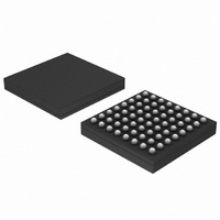
0W888-002-XTP ON Semiconductor, 0W888-002-XTP Datasheet - Page 18

0W888-002-XTP
Manufacturer Part Number
0W888-002-XTP
Description
DSP BELASIGNA 250 AUDIO 64LFBGA
Manufacturer
ON Semiconductor
Series
BelaSigna® 250r
Type
Floating Pointr
Datasheet
1.B250W48A106XXG.pdf
(33 pages)
Specifications of 0W888-002-XTP
Interface
I²C, I²S, PCM, SPI, UART
Clock Rate
50MHz
On-chip Ram
42kB
Voltage - I/o
1.0V, 2.0V
Voltage - Core
1.00V, 2.00V
Operating Temperature
-40°C ~ 85°C
Mounting Type
Surface Mount
Package / Case
64-LFBGA
Package
64LFBGA
Numeric And Arithmetic Format
Fixed-Point
Ram Size
16 KB
Lead Free Status / RoHS Status
Lead free / RoHS Compliant
Non-volatile Memory
-
Available stocks
Company
Part Number
Manufacturer
Quantity
Price
Company:
Part Number:
0W888-002-XTP
Manufacturer:
ON Semiconductor
Quantity:
10 000
Weighted Overlap−Add (WOLA) Filterbank Coprocessor
high−fidelity filterbank processing to provide efficient
time−frequency processing and alias−free gain adjustments.
The WOLA coprocessor stores intermediate data values as
well as program code and window coefficients in its own
memory space. Audio data are accessed directly from the
input and output FIFOs where they are automatically
managed by the IOP.
different sizes and types of transforms, such as mono, simple
stereo or full stereo configurations. The number of bands,
the stacking mode (even or odd), the oversampling factor
and the shape of the analysis and synthesis windows used are
all configurable. The selected set of parameters affects both
the frequency resolution, the group delay through the
WOLA coprocessor and the number of cycles needed for
complete execution.
complex data or energy values that represent the energy in
each band. Either real or complex gains can be applied to the
data. Complex gains provide means for phase adjustments,
which is useful in sub−band directional hearing aid
applications. The RCore always has access to these values
through shared memories. All parameters are configurable
with microcode, which is used to control the WOLA
coprocessor during execution.
application, synthesis) through dedicated control registers.
A dedicated interrupt is used to signal completion of a
WOLA function.
configurations are delivered with the BelaSigna 250
Evaluation
configurations have been specially designed for low group
delay and high fidelity.
The
The WOLA coprocessor can be configured to provide
The WOLA coprocessor can generate both real and
The RCore initiates all WOLA functions (analysis, gain
A large number of standard WOLA microcode
Time−domain
input
WOLA
and
coprocessor
Development
1. Filterbank
(Length: La)
Analysis
Figure 4. WOLA Filterbank Coprocessor Architecture
performs
Kit
(EDK).
Sampling
Down
R
R
R
low−delay,
(Real or Complex)
http://onsemi.com
(0 to Nyquist)
These
Application
N/2 bands
Processing
Processing
Processing
2. Gain
Band
Band
Band
18
Input/Output Processor (IOP)
for audio data samples. It manages the collection of data
from the A/D converters to the input FIFO and feeds digital
data to the audio output stage from the output FIFO.
shared with the RCore. Each FIFO (input and output) has
two memory interfaces. The first corresponds with the
normal FIFO. Here the address of the most recent input
block changes as new blocks of samples arrive. The second
corresponds with the Smart FIFO. In this scheme the address
of the most recent input block is fixed. The Smart FIFO
interface is especially useful for time−domain filters.
longer work together as a result of a low battery condition,
an IOP end−of−battery−life auto−mute feature is available.
four different audio modes that are shown in Figure 8.
•
•
•
•
Sampling
The IOP is an audio−optimized configurable DMA unit
The IOP places and retrieves FIFO data in memories
In the case where the WOLA coprocessor and the IOP no
The IOP can be configured to access data in the FIFOs in
Mono mode: Input samples are stored sequentially in
the input FIFO. Output samples are stored sequentially
in the output FIFO.
Simple stereo mode: Input samples from the two
channels are interleaved in the input FIFO. Output
samples for the single output channel are stored in the
lower part of the output FIFO.
Digital mixed mode: Input samples from the two
channels are stored in each half of the input FIFO.
Output samples for the single output channel are stored
in the lower half of the output FIFO.
Full stereo mode: Input samples from the two channels
are interleaved in the input FIFO. Output samples for
the two output channels are also interleaved in the
output FIFO.
Up
R
R
R
(Length: Ls = La/DF)
3. Filterbank
Synthesis
Time−domain
output


