EGN.2F.319.XLM LEMO, EGN.2F.319.XLM Datasheet - Page 17
EGN.2F.319.XLM
Manufacturer Part Number
EGN.2F.319.XLM
Description
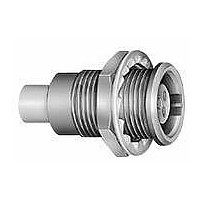
Circular Push Pull Connectors 19P RECEPT FEMALE CRIMP CONTACTS
Manufacturer
LEMO
Series
F Seriesr
Datasheet
1.FGN.0F.304.XLC.pdf
(48 pages)
Specifications of EGN.2F.319.XLM
Product Type
Connectors
Contact Style
Socket (Female)
Shell Style
Receptacle
Number Of Contacts
19
Lead Free Status / Rohs Status
Lead free / RoHS Compliant


HEN fixed sockets allow the device on which they are fitted to reach a protection index of IP68 as per IEC 60529 (unma-
ted). These models are identified by a letter «P» at the end of the reference. Epoxy resin is used to seal these models.
They can be mated with all plugs of the same series to achieve an IP67 protection index between the plug and socket.
Technical Characteristics
Mechanical and Climatical
Note:
www.lemo.com
Temperature range
Temperature range
Protection index unmated
Maximum operating pressure
1)
see also page 10.
Characteristics
3
E maxi
L
X
P
M
S 1
2
1)
2)
this value corresponds to the maximum allowed pressure difference for the assembled socket.
2)
S 2
N
E maxi
P
Epoxy resin
M
S 1
IP68
5 bars
S 2
Value
H
-15° C, +100° C
-50° C, +150° C
IEC 60529
IEC 60512-7 test 14d
HE
Panel cut-out (page 33)
Note:
HE
Panel cut-out (page 33)
Model
Model
HE
HE
HE
HE
HEN
HEP
HES
HET
HEW
HEX
HEW
HEX
HE
HE
HE
HE
●
●
Reference
Reference
●
●
●
●
●
●
●
●
Standard
1)
Fixed socket, nut fixing, key (N) or keys (P, S, T, W and X),
for printed circuit, (back panel mounting)
Fixed socket, nut fixing, key (N) or key (P),
with elbow (90°) contacts for printed circuit,
(back panel mounting)
fitted with notched nut GEG.
Series
Series
Watertight PCB models
FF
0F
1F
2F
3F
3F
3F
3F
4F
4F
LF
LF
5F
0F
1F
2F
1)
10 11
13 14 M10x0.75 3.0
17 17 M13x0.75 3.0
20 20 M16x1.00 3.0
22 23 M18x1.00 3.0 11.43 21.5 4.0 14.5 16.5 19.0 17.5
22 23 M18x1.00 3.0 11.43 21.5 4.0 14.5 16.5 19.0 17.5
22 23 M18x1.00 3.0 11.43 23.0 4.0 16.0 16.5 19.0 19.0
22 23 M18x1.00 3.0 11.43 23.0 4.0 16.0 16.5 19.0 19.0
29 29 M24x1.00 3.0 15.24 21.5 5.0 14.5 22.0 25.0 17.5
29 29 M24x1.00 3.0 15.24 23.5 5.0 16.5 22.0 25.0 19.5
32 32 M27x1.00 6.4 16.51 26.3 5.0 20.0 25.0 28.0 23.5
32 32 M27x1.00 6.4 16.51 26.3 5.0 20.0 25.0 28.0 23.5
38 38 M33x1.00 6.4 20.32 32.2 5.0 24.0 31.0 34.0 27.4
A
13
17
20
A
All; code X or Y
All; code C or variant with silicone gasket final code (S)
All
All
B
14
17
20
B
M7x0.50 3.0
M10x0.75
M13x0.75
M16x1.00
e
e
Series / Shell material
E
Dimensions (mm)
Dimensions (mm)
3.0
3.0
3.0
E
5.08 18.2 2.5 12.0 6.4 8.2 15.0
5.08 21.5 2.5 14.5 9.0 11.0 17.5
7.62 21.5 3.2 14.5 11.5 14.0 17.5
8.89 21.5 4.0 14.5 14.5 17.0 17.5
H
20
20
20
H
PCB drilling pattern (page 34)
PCB drilling pattern (page 35)
L
2.5 18.5 14.5
3.2 18.5 14.5 11.5 14
4.0 18.5 14.5 14.5 17
M
M
N
P
®
S1
P
S1
S2
9.0 11
S2
X
15
®
Related parts for EGN.2F.319.XLM
Image
Part Number
Description
Manufacturer
Datasheet
Request
R

Part Number:
Description:
RF Connectors ADAPTOR SOCKET TO BNC PLUG
Manufacturer:
LEMO
Datasheet:

Part Number:
Description:
RF Connectors ADAPT-BNC(UG88U)COAX
Manufacturer:
LEMO
Datasheet:
Part Number:
Description:
RF Connectors BNC ADAPTER 50 OHM
Manufacturer:
LEMO
Datasheet:

Part Number:
Description:
LEMO, SPRING LOADED DUSTCAP
Manufacturer:
LEMO
Datasheet:

Part Number:
Description:
Circular Push Pull Connectors CONNECTOR WRENCH FOR LEMO
Manufacturer:
LEMO
Part Number:
Description:
Specifications: Connector Type: Plug, Male Pins ; Shell Size - Insert: 114 ; Mounting Type: Free Hanging (In-Line) ; Fastening Type: Threaded ; Features: Shielded ; Packaging: Bulk ; Number of Positions: 114 ; Termination: Crimp ; Shell Material, Fin
Manufacturer:
LEMO
Part Number:
Description:
Specifications: Connector Style: - ; Connector Type: Plug ; Simplex/Duplex: Duplex ; Mode: Singlemode ; Fiber Diameter: 125
Manufacturer:
LEMO