M55302/166B10Y1 Amphenol, M55302/166B10Y1 Datasheet - Page 32
M55302/166B10Y1
Manufacturer Part Number
M55302/166B10Y1
Description
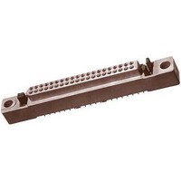
Board to Board / Mezzanine Connectors 3 ROW 10 CONT PER ROW MB-P TERM BRUSH
Manufacturer
Amphenol
Series
Low Mating Force Seriesr
Datasheet
1.M55302166C80X1.pdf
(33 pages)
Specifications of M55302/166B10Y1
Product Type
Receptacles
Pitch
2.54 mm
Mounting Style
Through Hole
Mounting Angle
Right
Number Of Positions / Contacts
10
Number Of Rows
3
Lead Free Status / Rohs Status
Lead free / RoHS Compliant


Low Mating Force — accessories
test probe kit
In order to insure that contacts are properly wired
within a connector, a Test probe Kit (11-10400-22)*
is needed. This kit is especially designed to prevent
damage to brush contacts during probing. It con-
sists of a plastic holder, insert, and two contacts,
usable for either Mother Board or Daughter Board
applications. It is recommended that the user buy
two kits, if using connectors of two genders. The
kits are not convertible after assembly.
Instructions:
DB-IO Test Probe -
MB-PC Test probe - Slide holder over wire and then
Crimping Procedure: Using accepted industry pro-
Insert stripped wire end into contact wire well.
*For ordering information, see page 7.
cedures, strip wire end to be terminated 1/8 to 5/32
inch. Care should be taken not to nick wire strands.
Assemble the M22520/2-01 crimp tool and the
M22520/2-27 positioner, and place tool selector in
correct setting for wire size. Selected wire size
must not have an insulation diameter more
than .062 for MB-PC and not more than .038 for
DB/IO.
Strands should be visible in wire well inspection
hole. Bottom contact and wire assembly in posi-
tioner, and close handles of crimp tool to complete
crimp. Handles will not open unless full crimping
cycle has been completed.
AWG
SEL
22
5
24
4
Slide the insert back over
the wire and crimp contact
on. Follow crimping proce-
dure below. Then snap the
insert and contact assembly
into the holder.
crimp contact. Follow crimp-
ing procedure below. Slide
the insert on the contact and
seat it against the shoulder.
Slide the holder forward and
snap it onto the insert.
26
3
28
2
30
.038
DIA. MIN.
.062
DIA. MIN.
DAUGHTER BOARD - INPUT/OUTPUT TEST PROBE
±.03
.18
MOTHER BOARD - PC TEST PROBE
.675 MAX.
.675 MAX.
.113 – .146
±.03
.18
.110
DIA. MAX.
.125
DIA. MAX.
.072
±.025
Related parts for M55302/166B10Y1
Image
Part Number
Description
Manufacturer
Datasheet
Request
R

Part Number:
Description:
Standard Card Edge Connectors DIN 96POS
Manufacturer:
AVX Corporation
Datasheet:
Part Number:
Description:
Connector,DIN-41612,PCB Mount,RECEPT,96 Contacts,PIN,0.1 Pitch,WRAP POST Terminal,HOLE .099-.111
Manufacturer:
AVX Corporation

Part Number:
Description:
Board to Board / Mezzanine Connectors POLARIZING KEY
Manufacturer:
Amphenol
Datasheet:
Part Number:
Description:
Cable Specification: PU CABLE, UL20549 24AWG*8C+AD,OD= 6.0mm
Manufacturer:
Amphenol