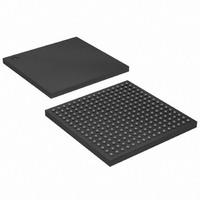
XC2S150E-6FT256I Xilinx Inc, XC2S150E-6FT256I Datasheet - Page 54

XC2S150E-6FT256I
Manufacturer Part Number
XC2S150E-6FT256I
Description
SPARTAN FPGA 150000 GATE 1.8V
Manufacturer
Xilinx Inc
Series
Spartan™-IIEr
Datasheet
1.XC2S50E-6TQG144C.pdf
(108 pages)
Specifications of XC2S150E-6FT256I
Number Of Logic Elements/cells
3888
Number Of Labs/clbs
864
Total Ram Bits
49152
Number Of I /o
182
Number Of Gates
150000
Voltage - Supply
1.71 V ~ 1.89 V
Mounting Type
Surface Mount
Operating Temperature
-40°C ~ 100°C
Package / Case
256-LBGA
Lead Free Status / RoHS Status
Contains lead / RoHS non-compliant
Other names
Q1280323
Available stocks
Company
Part Number
Manufacturer
Quantity
Price
Spartan-IIE FPGA Family: Pinout Tables
Pin Definitions (Continued)
54
D0/DIN, D1, D2, D3,
D4, D5, D6, D7
WRITE
CS
TDI, TDO, TMS, TCK
V
V
V
GND
IRDY, TRDY
L#[P/N]
(e.g., L0P)
L#[P/N]_Y
(e.g., L0P_Y)
L#[P/N]_YY
(e.g., L0P_YY)
I/O
CCINT
CCO
REF
Pad Name
Dedicated
Pin
Yes
Yes
Yes
Yes
No
No
No
No
No
No
No
No
No
Input or Output
documentation
See PCI core
Bidirectional
Bidirectional
Bidirectional
Bidirectional
Direction
Mixed
Input
Input
Input
Input
Input
Input
www.xilinx.com
In Slave Parallel mode, D0-D7 are configuration data input pins.
During readback, D0-D7 are output pins. These pins become
user I/Os after configuration unless the Slave Parallel port is
retained.
In serial modes, DIN is the single data input. This pin becomes a
user I/O after configuration.
In Slave Parallel mode, the active-low Write Enable signal. This
pin becomes a user I/O after configuration unless the Slave
Parallel port is retained.
In Slave Parallel mode, the active-low Chip Select signal. This pin
becomes a user I/O after configuration unless the Slave Parallel
port is retained.
Boundary Scan Test Access Port pins (IEEE 1149.1).
1.8V power supply pins for the internal core logic.
Power supply pins for output drivers (1.5V, 1.8V, 2.5V, or 3.3V
subject to banking rules in the
Input threshold reference voltage pins. Become user I/Os when
an external threshold voltage is not needed (subject to banking
rules in the
Ground. All must be connected.
These signals can only be accessed when using Xilinx PCI cores.
If the cores are not used, these pins are available as user I/Os.
Differential I/O with synchronous output. P = positive, N =
negative. The number (#) is used to associate the two pins of a
differential pair. Becomes a general user I/O when not needed for
differential signals.
Differential I/O with asynchronous or synchronous output
(asynchronous output not compatible for all densities in a
package). P = positive, N = negative. The number (#) is used to
associate the two pins of a differential pair. Becomes a general
user I/O when not needed for differential signals.
Differential I/O with asynchronous or synchronous output
(compatible for all densities in a package). P = positive, N =
negative. The number (#) is used to associate the two pins of a
differential pair. Becomes a general user I/O when not needed for
differential signals.
These pins can be configured to be input and/or output after
configuration is completed. Unused I/Os are disabled with a weak
pull-down resistor. After power-on and before configuration is
completed, these pins are either pulled up or left floating
according to the Mode pin values. See the
Characteristics
Functional Description
module for power-on characteristics.
Description
Functional Description
module.
DS077-4 (2.3) June 18, 2008
DC and Switching
Product Specification
module.
R


