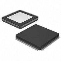
XCS30XL-4PQ208C Xilinx Inc, XCS30XL-4PQ208C Datasheet - Page 32

XCS30XL-4PQ208C
Manufacturer Part Number
XCS30XL-4PQ208C
Description
IC FPGA 3.3V C-TEMP HP 208PQFP
Manufacturer
Xilinx Inc
Series
Spartan™-XLr
Datasheet
1.XCS05XL-4VQG100C.pdf
(83 pages)
Specifications of XCS30XL-4PQ208C
Number Of Logic Elements/cells
1368
Number Of Labs/clbs
576
Total Ram Bits
18432
Number Of I /o
169
Number Of Gates
30000
Voltage - Supply
3 V ~ 3.6 V
Mounting Type
Surface Mount
Operating Temperature
0°C ~ 85°C
Package / Case
208-BFQFP
Case
QFP208
Dc
00+
Lead Free Status / RoHS Status
Contains lead / RoHS non-compliant
Available stocks
Company
Part Number
Manufacturer
Quantity
Price
Company:
Part Number:
XCS30XL-4PQ208C
Manufacturer:
XILINX
Quantity:
586
Part Number:
XCS30XL-4PQ208C
Manufacturer:
XILINX/赛灵思
Quantity:
20 000
Spartan and Spartan-XL FPGA Families Data Sheet
Legend:
32
Table 16: Spartan/XL Data Stream Formats
Notes:
1.
2.
3.
Fill Byte
Preamble Code
Length Count
Fill Bits
Field Check
Code
Start Field
Data Frame
CRC or Constant
Field Check
Extend Write
Cycle
Postamble
Start-Up Bytes
Unshaded
Light
Dark
Data Type
Not used by configuration logic.
11111111b for XCS40XL only.
Development system may add more start-up bytes.
(3)
Serial Modes
COUNT[23:0]
DATA[n–1:0]
xxxx (CRC)
11111111b
01111111b
or 0110b
Once per bitstream
Once per data frame
Once per device
(D0...)
0010b
1111b
FFh
0b
-
-
FFFFFFFFFFFFFFh
(Spartan-XL only)
COUNT[23:0]
Express Mode
FFD2FFFFFFh
11111110b
DATA[n–1:0]
11110010b
11010010b
11010010b
(D0-D7)
FFFFh
-
-
(2)
(1)
www.xilinx.com
A selection of CRC or non-CRC error checking is allowed by
the bitstream generation software. The Spartan-XL family
Express mode only supports non-CRC error checking. The
non-CRC
end-of-frame field for each frame. For CRC error checking,
the software calculates a running CRC and inserts a unique
four-bit partial check at the end of each frame. The 11-bit
CRC check of the last frame of an FPGA includes the last
seven data bits.
Detection of an error results in the suspension of data load-
ing before DONE goes High, and the pulling down of the
INIT pin. In Master serial mode, CCLK continues to operate
externally. The user must detect INIT and initialize a new
configuration by pulsing the PROGRAM pin Low or cycling
V
Cyclic Redundancy Check (CRC) for Configura-
tion and Readback
The Cyclic Redundancy Check is a method of error detec-
tion in data transmission applications. Generally, the trans-
mitting system performs a calculation on the serial
bitstream. The result of this calculation is tagged onto the
data stream as additional check bits. The receiving system
performs an identical calculation on the bitstream and com-
pares the result with the received checksum.
Each data frame of the configuration bitstream has four
error bits at the end, as shown in
error is detected during the loading of the FPGA, the config-
uration process with a potentially corrupted bitstream is ter-
minated. The FPGA pulls the INIT pin Low and goes into a
Wait state.
CC
.
error
checking
tests
DS060 (v1.8) June 26, 2008
Table
Product Specification
for
16. If a frame data
a
designated
R


