2001-5031-02 Tyco Electronics, 2001-5031-02 Datasheet - Page 2
2001-5031-02
Manufacturer Part Number
2001-5031-02
Description
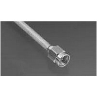
RF Connectors SMA PLUG RG-402/U
Manufacturer
Tyco Electronics
Datasheet
1.2001-7941-02.pdf
(3 pages)
Specifications of 2001-5031-02
Product
Connector
Rf Series
SMA
Gender
Plug
Contact Plating
Gold over Nickel
Shell Plating
Gold over Nickel
Body Style
Straight
Cable Type
405 Semi Rigid/3.58
Connector Type
Plug Connector
Housing Material
Stainless Steel
Maximum Frequency
18 GHz
Operating Temperature Range
- 65 C to + 165 C
Lead Free Status / Rohs Status
Lead free / RoHS Compliant
Other names
1050542-1


2.2. Soldering Cable to Plug Housing
2.3. Compressing the Expanded Dielectric
2.4. Removing the Outer Conductor and Dielectric
2.5. Trimming the End of Housing Subassembly
2 of 3
DANGER
DANGER
1. Place plug housing on the end of the cable.
2. Place the loose assembly in the fixture base
described in Figure 2.
3. Slide the housing against the locator tool.
4. Hold the the housing firmly against the locator
tool and solder as shown in Figure 4 with 60/40
solder.
1. Trim the extended or exposed dielectric flush
with the end of the cable outer conductor.
2. Place the dielectric recess tool on the dielectric
and push the tool to recess the dielectric within the
cable outer conductor. See Figure 5.
1. Insert the squared cable end into the fixture
base hole (hole pattern No. 1).
2. Place the saw in the saw slot and cut through
the the outer conductor and into the dielectric while
rotating the cable.
3. Remove the cable from the the fixture base and
finish cutting the dielectric with a cutting blade.
4. Bare the inner conductor by prying out the outer
conductor and dielectric from the cable.
1. Place the trim tool (see Figure 2) over the inner
conductor projection and rotate to face off the front
face.
2. Inspect for the dimensions shown in Figure 7.
(Optional)
a. Nest the cable end in the locator tool.
b. Tighten the clamp screw to secure the cable.
c. Tighten the locator tool to seat the cable
firmly.
Solder equipment is hot. To avoid personal injury,
be sure to exercise caution and follow all local
safety procedures when using soldering
equipment.
To avoid personal injury, be sure to wear gloves
and follow all local safety practices when using a
cutting blade.
(Figure 4)
Trim
Tool
Solder Here with 60/40 Solder
Dielectric Recess
Tool 1055450- - 1
Fixture Base
Assembly
Locator Tool
Figure 4
Figure 5
Figure 6
Figure 7
Housing Subassembly
Clamp Screw
Clamp Insert 1055440- - 1
Housing
Subassembly
2.39 +/- - .102
[.094 +/- - .004
Push
Saw
Slot
Hole Pattern
No. 1
4.62
[.182] Dia
408- 4761
Cable
Rev B
Related parts for 2001-5031-02
Image
Part Number
Description
Manufacturer
Datasheet
Request
R

Part Number:
Description:
RF Connectors SMA PLUG RG-405/U
Manufacturer:
Tyco Electronics
Datasheet:

Part Number:
Description:
RF Connectors SMA CABLE PLUG
Manufacturer:
Tyco Electronics
Datasheet:
Part Number:
Description:
RF Connectors SMA PLUG RG-402/U
Manufacturer:
Tyco Electronics
Datasheet:

Part Number:
Description:
RF Connectors SMA PLUG
Manufacturer:
Tyco Electronics
Datasheet:
Part Number:
Description:
RF Connectors SMA PLUG
Manufacturer:
Tyco Electronics
Datasheet:
Part Number:
Description:
RF Connectors Straight Cable Plug
Manufacturer:
Tyco Electronics
Part Number:
Description:
RF Connectors SMA ST CBL-PLG F/H SDR S
Manufacturer:
Tyco Electronics
Part Number:
Description:
RF Connectors SMA CABLE PLUG SMA-SSMA
Manufacturer:
Tyco Electronics

Part Number:
Description:
RF Connectors SMA ST PLG STD CBL SLDR SS/AU
Manufacturer:
Tyco Electronics

Part Number:
Description:
Manufacturer:
Tyco Electronics
Datasheet: