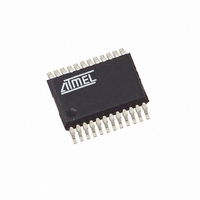
ATAM862P-TNQY3D Atmel, ATAM862P-TNQY3D Datasheet - Page 31

ATAM862P-TNQY3D
Manufacturer Part Number
ATAM862P-TNQY3D
Description
IC MCU FLASH 4K TX 315MHZ 24SSOP
Manufacturer
Atmel
Datasheet
1.ATAM862P-TNQY3D.pdf
(110 pages)
Specifications of ATAM862P-TNQY3D
Applications
UHF ASK/FSK
Core Processor
MARC4
Program Memory Type
FLASH (4 kB)
Controller Series
MARC4 4-Bit
Ram Size
256 x 4
Interface
SSI
Number Of I /o
11
Voltage - Supply
1.8 V ~ 4 V
Operating Temperature
-40°C ~ 125°C
Mounting Type
Surface Mount
Package / Case
24-SSOP
Processor Series
ATAM862x
Core
MARC4
Data Bus Width
4 bit
Mounting Style
SMD/SMT
Lead Free Status / RoHS Status
Lead free / RoHS Compliant
19.3.2
20. Power-down Modes
4554F–4BMCU–07/07
System Configuration Register (SC)
Table 19-4.
The sleep mode is a shut-down condition which is used to reduce the average system power
consumption in applications where the microcontroller is not fully utilized. In this mode, the sys-
tem clock is stopped. The sleep mode is entered via the SLEEP instruction. This instruction sets
the interrupt enable bit (I) in the condition code register to enable all interrupts and stops the
core. During the sleep mode the peripheral modules remain active and are able to generate
interrupts. The microcontroller exits the sleep mode by carrying out any interrupt or a reset.
The sleep mode can only be kept when none of the interrupt pending or active register bits are
set. The application of the $AUTOSLEEP routine ensures the correct function of the sleep
mode. For standard applications use the $AUTOSLEEP routine to enter the power-down mode.
Using the SLEEP instruction instead of the $AUTOSLEEP following an I/O instruction requires
to insert 3 non-I/O instruction cycles (for example NOP NOP NOP) between the IN or OUT com-
mand and the SLEEP command.
The total power consumption is directly proportional to the active time of the microcontroller. For
a rough estimation of the expected average system current consumption, the following formula
should be used:
I
I
SC: write
BOT
OS1
OS0
Note:
total
DD
Mode
depends on V
1
2
3
4
(V
DD
If the bit CCS = 0 in the CM register the RC-oscillator 1 always stops.
, f
syscl
OS1
Brown-Out Threshold
BOT = 1, low brown-out voltage threshold (1.7V)
BOT = 0, high brown-out voltage threshold (2.0V)
Oscillator Select 1
Oscillator Select 0
1
0
1
0
) = I
Oscillator Select
DD
Sleep
BOT
Bit 3
and f
OS0
1
1
0
0
+ (I
syscl
DD
Bit 2
---
× t
Input for SUBCL
active
32 kHz
C
C
C
Bit 1
OS1
/t
in
in
in/
total
/16
/16
16
)
Bit 0
OS0
Selected Oscillators
RC-oscillator 1 and external input clock
RC-oscillator 1 and RC-oscillator 2
RC-oscillator 1 and 4-MHz crystal oscillator
RC-oscillator 1 and 32-kHz crystal oscillator
Primary register address: "3"hex
Reset value: 1x11b
ATAM862-3
31


