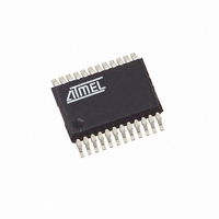
ATAM862P-TNSY8D Atmel, ATAM862P-TNSY8D Datasheet - Page 77

ATAM862P-TNSY8D
Manufacturer Part Number
ATAM862P-TNSY8D
Description
IC MCU FLASH 4K TX 868MHZ 24SSOP
Manufacturer
Atmel
Datasheet
1.ATAM862P-TNQY8D.pdf
(110 pages)
Specifications of ATAM862P-TNSY8D
Applications
UHF ASK/FSK
Core Processor
MARC4
Program Memory Type
FLASH (4 kB)
Controller Series
MARC4 4-Bit
Ram Size
256 x 4
Interface
SSI
Number Of I /o
11
Voltage - Supply
1.8 V ~ 4 V
Operating Temperature
-40°C ~ 125°C
Mounting Type
Surface Mount
Package / Case
24-SSOP
Processor Series
ATAM862x
Core
MARC4
Data Bus Width
4 bit
Mounting Style
SMD/SMT
Lead Free Status / RoHS Status
Lead free / RoHS Compliant
- Current page: 77 of 110
- Download datasheet (3Mb)
23.8.6
23.8.7
4590G–4BMCU–06/07
8-bit Pseudo MCL Mode
MCL Bus Protocol
Figure 23-20. Example of MCL Receive Dialog
In this mode, the SSI exhibits all the typical MCL operational features except for the acknowl-
edge-bit which is never expected or transmitted.
The MCL protocol constitutes a simple 2-wire bi-directional communication highway via which
devices can communicate control and data information. Although the MCL protocol can support
multi-master bus configurations, the SSI in MCL mode is intended for use purely as a master
controller on a single master bus system. So all reference to multiple bus control and bus con-
tention will be omitted at this point.
All data is packaged into 8-bit telegrams plus a trailing handshaking or acknowledge-bit. Nor-
mally the communication channel is opened with a so-called start condition, which initializes all
devices connected to the bus. This is then followed by a data telegram, transmitted by the mas-
ter controller device. This telegram usually contains an 8-bit address code to activate a single
slave device connected onto the I
its own unique address. The addressed slave device, if ready to receive data, will respond by
pulling the SD line low during the 9th clock pulse. This represents a so-called MCL acknowl-
edge. The controller detecting this affirmative acknowledge then opens a connection to the
required slave. Data can then be passed back and forth by the master controller, each 8-bit tele-
gram being acknowledged by the respective recipient. The communication is finally closed by
the master device and the slave device put back into standby by applying a stop condition onto
the bus.
(IFN = 0)
(IFN = 1)
Interrupt
Interrupt
SRDY
ACT
SDD
SIR
SD
SC
Write STB
(tx data 1)
Start
msb
7 6 5 4 3 2 1
tx data 1
2
C bus. Each slave receives this address and compares it with
lsb
0 A
msb
7 6 5 4 3 2 1 0 A
rx data 2
lsb
ATAM862-8
Stop
Read SRB
(rx data 2)
77
Related parts for ATAM862P-TNSY8D
Image
Part Number
Description
Manufacturer
Datasheet
Request
R

Part Number:
Description:
IC MCU FLASH 4K TX 315MHZ 24SSOP
Manufacturer:
Atmel
Datasheet:

Part Number:
Description:
IC MCU FLASH 4K TX 433MHZ 24SSOP
Manufacturer:
Atmel
Datasheet:

Part Number:
Description:
IC MCU FLASH 4K TX 868MHZ 24SSOP
Manufacturer:
Atmel
Datasheet:

Part Number:
Description:
IC MCU FLASH 4K TX 315MHZ 24SSOP
Manufacturer:
Atmel
Datasheet:

Part Number:
Description:
IC MCU FLASH 4K TX 433MHZ 24SSOP
Manufacturer:
Atmel
Datasheet:

Part Number:
Description:
DEV KIT FOR AVR/AVR32
Manufacturer:
Atmel
Datasheet:

Part Number:
Description:
INTERVAL AND WIPE/WASH WIPER CONTROL IC WITH DELAY
Manufacturer:
ATMEL Corporation
Datasheet:

Part Number:
Description:
Low-Voltage Voice-Switched IC for Hands-Free Operation
Manufacturer:
ATMEL Corporation
Datasheet:

Part Number:
Description:
MONOLITHIC INTEGRATED FEATUREPHONE CIRCUIT
Manufacturer:
ATMEL Corporation
Datasheet:

Part Number:
Description:
AM-FM Receiver IC U4255BM-M
Manufacturer:
ATMEL Corporation
Datasheet:

Part Number:
Description:
Monolithic Integrated Feature Phone Circuit
Manufacturer:
ATMEL Corporation
Datasheet:

Part Number:
Description:
Multistandard Video-IF and Quasi Parallel Sound Processing
Manufacturer:
ATMEL Corporation
Datasheet:


