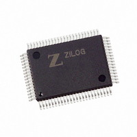
Z8018010FEG Zilog, Z8018010FEG Datasheet - Page 25

Z8018010FEG
Manufacturer Part Number
Z8018010FEG
Description
IC Z180 MPU 80QFP
Manufacturer
Zilog
Datasheet
1.Z8018006PSG.pdf
(85 pages)
Specifications of Z8018010FEG
Processor Type
Z180
Speed
10MHz
Voltage
5V
Mounting Type
Surface Mount
Package / Case
80-QFP
Processor Series
Z8018xx
Core
Z80
Data Bus Width
8 bit
Maximum Clock Frequency
10 MHz
Number Of Timers
2
Operating Supply Voltage
0 V to 5 V
Maximum Operating Temperature
+ 100 C
Mounting Style
SMD/SMT
Minimum Operating Temperature
- 40 C
Lead Free Status / RoHS Status
Lead free / RoHS Compliant
Features
-
Lead Free Status / Rohs Status
Details
Available stocks
Company
Part Number
Manufacturer
Quantity
Price
PS014004-1106
Note:
SLEEP Mode—Enter
CPU Control Register (
oscillator and
channels to reduce power consumption. DRAM refresh stops but interrupts and
granting to external master can occur. Except when the bus is granted to an external master,
A19–0
tions continue as before the
The Z80180 leaves
interrupt request from an on-chip source, an external request on
on
If an interrupt source is individually disabled, it cannot bring the Z80180 out of
mode. If an interrupt source is individually enabled, and the
globally enabled (by an
return address being the instruction after the
vidually enabled, but the
tion), the Z80180 leaves
This provides a technique for synchronization with high- speed external events without
incurring the latency imposed by an interrupt response sequence.
timing for exiting
IOSTOP Mode—IOSTOP
Register (
the CPU continues to operate. Recovery from
in
SYSTEM STOP Mode—SYSTEM STOP
modes.
INT
ICR
INT0
A
HALT
i
0
, NMI
–A
M1
and all control signals except
to
19
SYSTEM STOP
,
φ
The Z80180 takes about 1.5 clocks to restart.
INT1
0
ICR
.
T
2
SLEEP 2nd Opcode
Fetch Cycle
) to
PHI
, or
SLEEP 2nd Opcode Address
1
INT2
SLEEP
output continue operating, but are blocked from the CPU core and DMA
. In this case, on-chip I/O (
T
SLEEP
3
.
mode is entered by setting the
CCR3
SLEEP
EI
Figure 14. SLEEP Timing
SLEEP
IEF
mode due to an interrupt request.
mode is entered by setting the
instruction), the highest priority active interrupt occurs, with the
mode in response to a Low on
T
SLEEP
1
,
bit is
CCR6
mode by keeping the
mode by simply executing the following instruction(s).
0
T
instruction, except for the DMA channels.
) all zero and executing the
2
HALT
so that interrupts are globally disabled (by a
SLEEP Mode
mode is the combination of
T
are maintained High.
S
SLEEP
ASCI
FFFFFh
IOSTOP
T
,
instruction. If an interrupt source is indi-
S
CSIO
IOSTOP
IOSTOP
mode is by resetting the
IOSTOP
,
RESET
PRT
T
1
IEF
bit (
Opcode Fetch or Interrupt
Acknowledge Cycle
) stops operating. However,
bit in
SLEEP
bit is
NMI
, an
HALT
bit of the I/O Control
ICR5
Figure 14
T
Microprocessor Unit
2
ICR
, or an external request
SLEEP
1
) bits
instruction. The
so that interrupts are
is Low. I/O opera-
to
T
1
3
displays the
3
and
followed by
and
IOSTOP
SLEEP
Architecture
IOSTOP
DI
6
Z80180
of the
instruc-
bit
19


