TQ2-L-6V Panasonic, TQ2-L-6V Datasheet
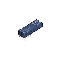
TQ2-L-6V
Specifications of TQ2-L-6V
Available stocks


Related parts for TQ2-L-6V


TQ2-L-6V Summary of contents
Page 1
... Tape and reel packing (picked from the 6/7/8/9/10-pin side) Notes: 1. *48 V coil type: Single side stable only 2. In case transistor drive circuit recommended to use 4.5 V type relay. All Rights Reserved © COPYRIGHT Panasonic Electric Works Co., Ltd. Leading the market, our 5 mm 2-pole surface ...
Page 2
... However, please contact us if you need parts for use in low level load. 2. M.B.B. type 1) Standard PC board terminal Contact arrangement 2 Form C Standard packing: Tube: 50 pcs.; Case: 1,000 pcs. 1 coil latching Part No. TQ2-3V TQ2-L-3V TQ2-4.5V TQ2-L-4.5V TQ2-5V TQ2-L-5V TQ2-6V TQ2-L-6V TQ2-9V TQ2-L-9V TQ2-12V TQ2-L-12V TQ2-24V TQ2-L-24V TQ2-48V TQ4-3V TQ4-L-3V TQ4-4.5V TQ4-L-4.5V TQ4-5V TQ4-L-5V TQ4-6V ...
Page 3
... TQ2S -L-1.5V-Z TQ2S -3V-Z TQ2S -L-3V-Z TQ2S -4.5V-Z TQ2S -L-4.5V-Z TQ2S -5V-Z TQ2S -L-5V-Z TQ2S -6V-Z TQ2S -L-6V-Z TQ2S -9V-Z TQ2S -L-9V-Z TQ2S -12V-Z TQ2S -L-12V-Z TQ2S -24V-Z TQ2S -L-24V-Z TQ2S -48V-Z Nominal operating current ( 10%] ( 46.7mA 31.1mA 28.1mA 23.3mA 15.5mA (Initial) 11 ...
Page 4
... Reset coil 133mA 133mA 88.9mA 88.9mA 80mA 80mA 66.6mA 66.6mA (Initial) 44.4mA 44.4mA 33.3mA 33.3mA 16.7mA 16.7mA All Rights Reserved © COPYRIGHT Panasonic Electric Works Co., Ltd. Coil resistance Nominal operating 68 F) power 90 202.5 250 100mW 360 810 1,440 3,840 150mW Coil resistance ...
Page 5
... Drop-out voltage voltage ( 1. 4. 75%V or less of 10%V or more nominal voltage* nominal voltage (Initial) 12V DC 24V DC 48V DC All Rights Reserved © COPYRIGHT Panasonic Electric Works Co., Ltd. Nominal operating current ( 10%] ( 66.7mA 44.4mA 40mA 33.3mA (Initial) 22.2mA 16.7mA 8.3mA 2 Form C, 2 Form D (M.B.B.) 2 Standard (B.B.M) type: 140 DC), 200 mW (24 V DC), 300 mW (48 V DC) M ...
Page 6
... A 125 V AC resistive) (at 20 cpm) Ambient temperature: 2 – +85 C – +185 Humidity 85% R.H. (Not freezing and condensing at low temperature) 20 cpm Approx .071 oz All Rights Reserved © COPYRIGHT Panasonic Electric Works Co., Ltd. Coil resistance Nominal operating 68 F) power 32 128.6 289.3 357 ...
Page 7
... Change of pick-up and drop-out voltage 100 90 80 Pick-up voltage Max. 70 Min Drop-out voltage Max. 30 Min No. of operations Ambient temperature characteristics Tested sample: TQ2-12V, 5 pcs Drop-out x voltage Pick-up voltage -40 - Ambient -10 temperature, C -20 -30 -40 8. Malfunctional shock (single side stable) Tested sample: TQ2-12V, 6 pcs. ...
Page 8
... Pick-up voltage Max. 70 Min Drop-out voltage 20 Max. Min 500 1,000 1,500 2,000 No. of operations 13. Distribution of M.B.B. time Tested sample: TQ2-2M-5V, 85 pcs. 60 Terminal Nos. 2-3- 105 163 n-1 Min Max.: 243 s Terminal Nos. 7-8- 115 167.3 s n-1 30 Min Max.: 254 s 21 ...
Page 9
... Drop-out voltage 30 Max. 20 Min IRS 1 10 100 1,000 10,000 4 No. of operations, 10 4.-(2) Electrical life (0.5 A 125 V AC resistive load) Tested sample: TQ2SA-12V, 6 pcs Operating speed: 20 cpm Change of pick-up and drop-out voltage (mounting by IRS method) 100 Pick-up voltage Max. 60 Min Drop-out voltage Max. ...
Page 10
... Direction indication (Deenergized condition) .012 All Rights Reserved © COPYRIGHT Panasonic Electric Works Co., Ltd. 10.-(2) Influence of adjacent mounting Tested sample: TQ2SA-12V, 6 pcs Pick-up voltage 0 –10 10 Drop-out voltage 0 – .039 .079 ...
Page 11
... Schematic (Top view) Single side stable 1-coil latching Direction indication Direction indication (Deenergized condition) (Reset condition) All Rights Reserved © COPYRIGHT Panasonic Electric Works Co., Ltd. 26.7 9 1.051 .354 0.5 0.25 .020 7.62 .010 2.54 .100 .300 26.7 9 1.051 ...
Page 12
... For general cautions for use, please refer to the “Cautions for inch use of Signal Relays” or “General Application Guidelines”. 0.3 .012 inch dia. .079 dia. All Rights Reserved © COPYRIGHT Panasonic Electric Works Co., Ltd. ...