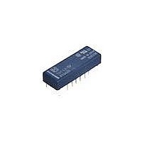
TQ2SA-6V-Z Panasonic, TQ2SA-6V-Z Datasheet - Page 9

TQ2SA-6V-Z
Manufacturer Part Number
TQ2SA-6V-Z
Description
Low Signal Relays - PCB Low Profile 6V 2Form C 2A 30VDC SMD
Manufacturer
Panasonic
Datasheet
1.TQ2-4.5V.pdf
(12 pages)
Specifications of TQ2SA-6V-Z
Contact Form
2 Form C
Coil Voltage
6 VDC
Coil Current
23.3 mA
Coil Type
Single Side Stable
Power Consumption
140 mW
Contact Carry Current
2 A
Termination Style
Solder Pad
Isolation
20 dB at 1 GHz
Insertion Loss
0.8 dB at 1 GHz
Maximum Switching Current
2 A
Contact Rating
2 A at 30 VDC / 500 mA at 125 VAC
Lead Free Status / Rohs Status
Lead free / RoHS Compliant
■ Surface-mount terminal
1. Maximum switching capacity
4.-(1) Electrical life (2 A 30 V DC resistive load)
Tested sample: TQ2SA-12V, 6 pcs.
Operating speed: 20 cpm
Change of pick-up and drop-out voltage
(mounting by IRS method)
Change of contact resistance
(mounting by IRS method)
7. Ambient temperature characteristics
Tested sample: TQ2SA-12V, 5 pcs.
100
100
3.0
2.0
1.0
0.5
0.4
0.3
0.2
90
80
70
60
50
40
30
20
10
90
80
70
60
50
40
30
20
10
0
0
0
AC resistive load
IRS
IRS
–40 –20
20 30
1
1
2
2
No. of operations, 10
No. of operations, 10
3
3
0
Contact voltage, V
Pick-up voltage
Drop-out voltage
50
4
4
20 40
–20
–40
40
20
5
5
DC resistive load
100
Ambient
temperature, C
6
6
Pick-up voltage
7
7
60
Drop-out voltage
200 300
8
8
4
4
80
x
9
9
All Rights Reserved © COPYRIGHT Panasonic Electric Works Co., Ltd.
10
10
Max.
Min.
Max.
Min.
Max.
Min.
2. Life curve
Change of contact resistance
(mounting by IRS method)
5. Coil temperature rise
Tested sample: TQ2SA-12V, 6 pcs.
Point measured: Inside the coil
Ambient temperature: 25 C
8.-(1) High-frequency characteristics
(Isolation)
100
100
100
90
80
70
60
50
40
30
20
10
50
50
30
20
10
70
60
50
40
30
20
10
0
0
0
IRS
Coil voltage
100
125V AC
resistive load
1
DC 12V type
DC 48V type
110
2
Coil applied voltage, %V
10
No. of operations, 10
3
Switching current, A
1.0
120
Frequency, MHz
4
77 F
5
130 140
30V DC
resistive load
6
100
7
2.0
8
150
4
2A
0A
2A
0A
9
1,000
10
Max.
Min.
3. Mechanical life (mounting by IRS method)
Tested sample: TQ2SA-12V, 10 pcs.
4.-(2) Electrical life (0.5 A 125 V AC resistive load)
Tested sample: TQ2SA-12V, 6 pcs
Operating speed: 20 cpm
Change of pick-up and drop-out voltage
(mounting by IRS method)
6. Operate/release time
Tested sample: TQ2SA-12V, 6 pcs.
8.-(2) High-frequency characteristics
(Insertion loss)
100
100
1.0
0.8
0.6
0.4
0.2
90
80
70
60
50
40
30
20
10
90
80
70
60
50
40
30
20
10
0
0
5
4
3
2
1
0
IRS
70
IRS
1
Max.
Max.
Min.
Min.
1
80
2
10
Coil applied voltage, %V
10
No. of operations, 10
No. of operations, 10
3
90
Pick-up voltage
Drop-out voltage
4
Frequency, MHz
Pick-up voltage
Drop-out voltage
100
100
5
6
100
110
1,000
7
8
Operate time
Release time
120
4
4
9
10,000
1,000
10
Max.
Min.
Max.
Min.
TQ
Max.
Min.
Max.
Min.


