W172DIP-24 Magnecraft / Schneider Electric, W172DIP-24 Datasheet - Page 7
W172DIP-24
Manufacturer Part Number
W172DIP-24
Description
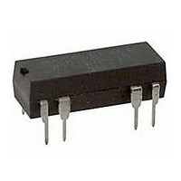
Reed Relay DPDT W/DIODE 24V
Manufacturer
Magnecraft / Schneider Electric
Type
Reed Relays / DIPr
Datasheet
1.W117SIP-6.pdf
(22 pages)
Specifications of W172DIP-24
Contact Form
DPDT
Maximum Switched Current
0.5 A
Coil Resistance
2200 Ohms
Contact Rating
0.288 W
Coil Voltage Vdc Nom
24V
Switching Current Max
250mA
Switching Voltage Max
100VDC
Contact Configuration
DPDT
Relay Mounting
PCB
External Height
10.16mm
Rohs Compliant
Yes
Lead Free Status / Rohs Status
Lead free / RoHS Compliant
Other names
172DIP-24


THERMAL EMF
Since thermally generated voltages result from thermal
gradients within the relay assembly, relays built to minimize
this effect often use sensitive switches to reduce required
coil power, and thermally conductive materials to reduce
temperature gradients. Latching relays, which may be
operated by a short duration pulse, are often used if the
operational rate is not changed for longer periods of time
because coil power is not required to keep the relay in the
on or off position after the initial turn on or turn off pulse.
NOISE
Noise is defined as a voltage appearing between terminals
of a switch for a few milliseconds following closure of the
contacts. It occurs because the reeds (blades) are moving
in a magnetic field and because voltages are produced
within them by magnetostrictive effects. From an
application standpoint, noise is important if the signal
switched by the reed is to be used within a few milliseconds
immediately following closure of the contacts. When noise
is critical in an application, a peak-to-peak limit must be
established by measurement techniques, including filters
which must be specified for that particular switching
application.
ENVIRONMENTAL CHARACTERISTICS
Reed relays are used in essentially the same environments
as other types of relays. Factors influencing their ability
to function would be temperature extremes beyond
specified limits
VIBRATION
The reed switch structure, with so few elements free to
move, has a better defined response to vibration than
other relay types. With vibration inputs reasonably
separated from the resonant frequency, the reed relay will
withstand relatively high inputs, 20 g's or more. At
resonance of the reeds, the typical device can fail at very
low input levels. Typical resonance frequency is 2000 hz.
SHOCK
Dry reed relays will withstand relatively high levels of
shock. SPST-NO contacts are usually rated to pass 30 to
50 g's, 11 milliseconds, half sign wave shock, without false
operation of contacts. Switches exposed to a magnetic
field that keep the contacts in a closed position, such as
in the biased latching form, demonstrate somewhat lower
resistance to shock. Normally closed contacts of
mechanically biased SPDT switches may also fail at lower
shock levels.
REED RELAYS
APPLICA
APPLICA
U. S.
TELEPHONE: (843)393-5778
FAX:
WEBSITE:
EMAIL:
EUROPE
TELEPHONE: 4989 / 75080310
FAX:
WEBSITE:
EMAIL:
TEMPERATURE
Differential expansion or contraction of reed switches and
materials used in relay assemblies can lead to fracture of
the switches. Reed relays are capable of withstanding
temperature cycling or temperature shock over a range of
at least -50˚C to + 100˚C. These limits should be applied to
the application to prevent switch failure.
CONTACT PROTECTION
Tungsten lamp, inductive and capacitive discharge load
are extremely detrimental to reed switches and reduce life
considerably. Illustrated below are typical suppression
circuits which are necessary for maximum contact life.
INPUT
Initial cold filament turn-on current is often 16 times higher
than the rated operating current of the lamp. A current
limiting resistor in series with the load, or a bleeder resistor
across the contacts will suppress the inrush current. The
same circuits can be used with capacitive loads, as shown
in Figure 3.
INPUT
DC inductive loads call for either a diode or a thyristor to
be placed across the load. These circuits are necessary
to protect the contacts when inductive loads are to be
switched in a circuit, as shown in Figure 4.
U. S.
EUROPE
A.
A.
R
info@magnecraft.com
renatesteinback@magnecraft.de
www.magnecraft.com
www.magnecraft.com
(843)393-4123
4989/ 7559344
TION DA
TION DA
Figure 3
Figure 4
INPUT
INPUT
T
R
T
A
A
6...
6
Related parts for W172DIP-24
Image
Part Number
Description
Manufacturer
Datasheet
Request
R

Part Number:
Description:
Reed Relay SPDT W/DIODE 12V
Manufacturer:
Magnecraft / Schneider Electric
Datasheet:
Part Number:
Description:
Reed Relay DPDT W/DIODE 5V
Manufacturer:
Magnecraft / Schneider Electric
Datasheet:
Part Number:
Description:
Reed Relay SPDT DIP 5V
Manufacturer:
Magnecraft / Schneider Electric
Datasheet:
Part Number:
Description:
Reed Relay SPDT W/DIODE 12V
Manufacturer:
Magnecraft / Schneider Electric
Datasheet:
Part Number:
Description:
Reed Relay SPDT DIP 12V
Manufacturer:
Magnecraft / Schneider Electric
Datasheet:
Part Number:
Description:
Reed Relay SPDT W/DIODE 24V
Manufacturer:
Magnecraft / Schneider Electric
Datasheet:
Part Number:
Description:
Reed Relay SPDT DIP 12V
Manufacturer:
Magnecraft / Schneider Electric
Datasheet:

Part Number:
Description:
Reed Relay SPDT W/DIODE 24V
Manufacturer:
Magnecraft / Schneider Electric
Datasheet:
Part Number:
Description:
Reed Relay SPDT DIP 12V
Manufacturer:
Magnecraft / Schneider Electric
Datasheet:
Part Number:
Description:
Reed Relay SPDT DIP 5V
Manufacturer:
Magnecraft / Schneider Electric
Datasheet:
Part Number:
Description:
Reed Relay DPDT W/DIODE 12V
Manufacturer:
Magnecraft / Schneider Electric
Datasheet:
Part Number:
Description:
Reed Relay SPDT W/DIODE 5V
Manufacturer:
Magnecraft / Schneider Electric
Datasheet:
Part Number:
Description:
Reed Relay SPDT W/DIODE 5V
Manufacturer:
Magnecraft / Schneider Electric
Datasheet:
Part Number:
Description:
Reed Relay SPDT W/DIODE 12V
Manufacturer:
Magnecraft / Schneider Electric
Datasheet:

Part Number:
Description:
Relay; E-Mech; Power; On Delay; SPDT; Cur-Rtg 15A; Ctrl-V 120AC; Vol-Rtg 240/24AC/DC
Manufacturer:
Magnecraft/Schneider Electric
Datasheet: