HS16-5N-RO NKK Switches, HS16-5N-RO Datasheet
HS16-5N-RO
Specifications of HS16-5N-RO


Related parts for HS16-5N-RO


HS16-5N-RO Summary of contents
Page 1
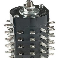
... Shown with panel cutouts in following drawings Manual Soldering (HS series only): See Profile A in Supplement section. File No. E44145 HS16 models 1– through 6–pole are recognized at 12A @ 125V AC & 250V AC See Supplement section to find UL or cULus rating details. Add “/U” to end of part number to order UL mark on switch. ...
Page 2
... HS16-4S HS16-4N HS16-5 HS16-5S HS16-5N HS16-6 HS16-6S HS16-6N Switch is viewed from shaft end and shown in position 1. Terminal numbers are not on switch. Standard Hardware shown on last page of this section. * Wire harness & cable assemblies offered only in Americas. (6.0) Dia .236 (65.0) 2.559 (4 ...
Page 3
Series TS 6 AMP/NONSHORTING/ADJUSTABLE STOP/30° INDEXING Number of Model Pole Positions TS1N 1P 2-11 TS2N 2P 2-11 TS3N 3P 2-11 TS4N 4P 2-11 TS5N 5P 2-11 • Standard Hardware shown on last page of this section. Panel Cutouts G (10.3) ...
Page 4
Standard Size Rotaries 30 AMP/NONSHORTING/ADJUSTABLE STOP/30° INDEXING Number of Knurled D Flat Shaft Shaft Pole Positions PS1 PS1N 1P 2-11 PS2 PS2N 2P 2-11 PS3 PS3N 3P 2-11 PS4 PS4N 4P 2-11 PS5 PS5N 5P 2-11 On each deck of ...
Page 5
... M2.3 x 0.4 x 8.0 For HS16, TS, & PS Models The HS16, TS, and PS switches are supplied with the stopper plate set for the maximum number of positions allowed for that model. Prior to installation, the desired stopper setting should be made sure the shaft is turned counterclockwise to the extreme left. If the shaft is not turned counterclockwise to the extreme left, proper setting cannot be achieved ...