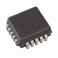
ATF16V8C-5JC Atmel, ATF16V8C-5JC Datasheet - Page 7

ATF16V8C-5JC
Manufacturer Part Number
ATF16V8C-5JC
Description
IC PLD 5NS 20PLCC
Manufacturer
Atmel
Datasheet
1.ATF16V8C-7PU.pdf
(23 pages)
Specifications of ATF16V8C-5JC
Programmable Type
EE PLD
Number Of Macrocells
8
Voltage - Input
5V
Speed
5ns
Mounting Type
Surface Mount
Package / Case
20-PLCC
Lead Free Status / RoHS Status
Contains lead / RoHS non-compliant
Other names
ATF16V8C5JC
Available stocks
Company
Part Number
Manufacturer
Quantity
Price
Company:
Part Number:
ATF16V8C-5JC
Manufacturer:
ATM
Quantity:
3 000
Company:
Part Number:
ATF16V8C-5JC
Manufacturer:
ATM
Quantity:
3 000
Company:
Part Number:
ATF16V8C-5JC
Manufacturer:
ATMEL
Quantity:
1 000
0425H–PLD–3/11
11.
12.
Security fuse usage
A single fuse is provided to prevent unauthorized copying of the ATF16V8C fuse patterns. Once programmed, fuse verify
and preload are inhibited. However, the 64-bit user signature remains accessible.
The security fuse will be programmed last, as its effect is immediate.
Input and I/O pin-keeper circuits
The ATF16V8C contains internal input and I/O pin-keeper circuits. These circuits allow each ATF16V8C pin to hold its
previous value even when it is not being driven by an external source or by the device’s output buffer. This helps insure
that all logic array inputs are at known, valid logic levels. This reduces system power by preventing pins from floating to
indeterminate levels. By using pin-keeper circuits rather than pull-up resistors, there is no DC current required to hold the
pins in either logic state (high or low).
These pin-keeper circuits are implemented as weak feedback inverters, as shown in the Input Diagram below. These
keeper circuits can easily be overdriven by standard TTL- or CMOS-compatible drivers. The typical overdrive current
required is 40μA.
Figure 13.
Figure 14.
Input diagram
I/O diagram
Atmel ATF16V8C
7


