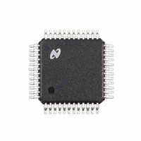
LM4549VH National Semiconductor, LM4549VH Datasheet - Page 14

LM4549VH
Manufacturer Part Number
LM4549VH
Description
IC CODEC AC '97 REV 2.1 48LQFP
Manufacturer
National Semiconductor
Type
Audio Codec '97r
Specifications of LM4549VH
Data Interface
Serial
Resolution (bits)
18 b
Number Of Adcs / Dacs
2 / 2
Sigma Delta
Yes
Dynamic Range, Adcs / Dacs (db) Typ
90 / 89
Voltage - Supply, Analog
4.2 V ~ 5.5 V
Voltage - Supply, Digital
3 V ~ 5.5 V
Operating Temperature
-40°C ~ 85°C
Mounting Type
Surface Mount
Package / Case
48-LQFP
Single Supply Voltage (typ)
3.3/5V
Single Supply Voltage (min)
3/4.2V
Single Supply Voltage (max)
5.5V
Package Type
LQFP
Lead Free Status / RoHS Status
Contains lead / RoHS non-compliant
Other names
*LM4549VH
Available stocks
Company
Part Number
Manufacturer
Quantity
Price
Company:
Part Number:
LM4549VH
Manufacturer:
NATIONAL
Quantity:
27
Part Number:
LM4549VHX
Manufacturer:
NS/国半
Quantity:
20 000
www.national.com
Application Information
SDATA_IN Slot 1: Status Address / Slot Request Bits
This slot echoes the control register which a read was re-
quested on. The address echoed was initiated by a read re-
quest in the previous SDATA_OUT frame, slot 1. Bits 11 and
10 are slot request bits that support Sample Rate Conver-
sion (SRC) functionality. If bit 11 is set to 0, then the control-
ler should respond with a valid PCM left sample in slot 3 of
the next frame. If bit 10 is set to 0, then the controller should
respond with a valid PCM right sample in slot 4 of the next
frame. If bits 11 or 10 are set to 1, the controller should not
send data in the next frame. Bits 9 through 2 are unused.
Bits 1 and 0 are reserved and should be set to 0.
18:12
Bits
Bit
15
14
13
12
11
19
11
10
FIGURE 7. Start of Audio Input Frame
Register Index
Codec Ready
Description
Description
Request bit
Request bit
(PCM right)
Slot 1 data
Slot 2 data
Slot 3 data
Slot 4 data
(PCM left)
Reserved
Control
Slot 3
Slot 4
valid
valid
valid
valid
Bit
Right Audio PCM Data is
Echo of Control Register
Left Audio PCM Data is
send valid slot 3 data in
send valid slot 4 data in
0=Not Ready, 1=Ready
Status Address is valid
for which data is being
send slot 3 data in the
send slot 4 data in the
0 = Controller should
Controller should not
0 = Controller should
Controller should not
Status Data is valid
the next frame, 1 =
the next frame, 1 =
Stuffed with 0
next frame
next frame
Comment
Comment
returned.
(Continued)
valid
valid
DS101035-7
14
SDATA_IN Slot 2: Status Data
The slot returns the control register data. The data returned
was initiated by a read request in the previous SDATA_OUT
frame, slot 1.
SDATA_IN Slot 3: PCM Record Left Channel
This slot contains the left ADC sample data. The signal to be
digitized is selected via register 1Ah and subsequently
routed through the Input Mux for recording by the left ADC.
This is a 20-bit slot, where the digitized 18-bit PCM data is
output from the codec MSB first and the last remaining 2 bits
will zeros.
SDATA_IN Slot 4: PCM Record Right Channel
This slot contains the right ADC sample data. The signal digi-
tized is selected via register 1Ah and subsequently routed
through the Input Mux for recording by the right ADC. This is
a 20-bit slot, where the digitized 18-bit PCM data is output
from the codec MSB first and the last remaining 2 bits will ze-
ros.
SDATA_IN Slots 5-12: Reserved
These SDATA_IN slots are set to 0 as they are reserved for
future use.
AC Link Low Power Mode
Bits
Bits
19:4
Bits
19:2
Bits
19:2
9:2
1,0
3:0
1:0
1:0
FIGURE 8. AC Link Powerdown Timing
Register Read
Right Channel
PCM Record
Left Channel
PCM Record
Request bits
Description
Description
Description
Description
Other Slot
Reserved
Reserved
Reserved
Reserved
Control
Data
data
data
18 bit audio sample from
18 bit audio sample from
Unused - stuff with 0
Stuffed with 0 ’s
Stuffed with 0 ’s
Stuffed with 0 ’s
Stuff with 0
Comment
Comment
Comment
Comment
right ADC
left ADC
DS101035-9


